Mechanical Design
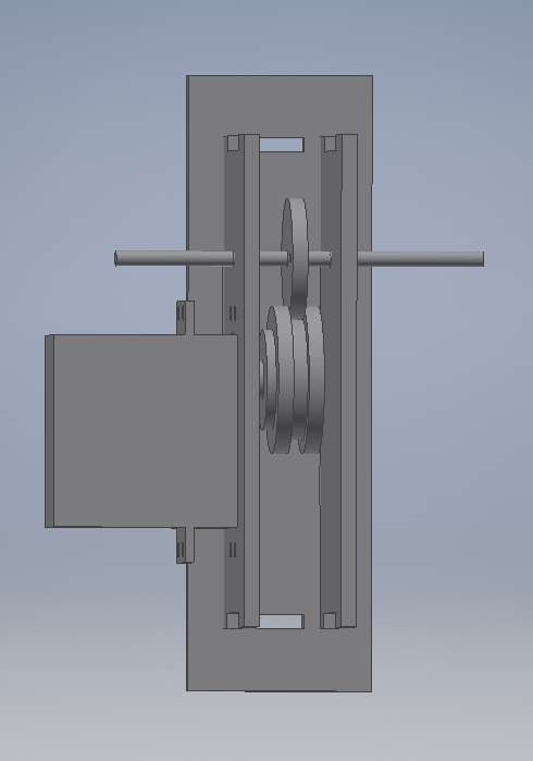
Fig. 1: Mechanical Drawing of Shade Drive Unit
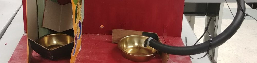
The primary mechanical portion of the design is the shade drive system depicted in Fig. 1. This system is designed to be laser-cut from 1/8in particle-board or acrylic. It consists of a primary drive pulley and idler wheel, which should have the ring magnet attached to it. The shade pull string should go between these pulleys, so that when the cable jams, the idler wheel will stop spinning and the system will detect a jam. We also found that wrapping a rubber band around the drive pulley significantly improved performance by reducing slippage.
The other mechanical portion is the enclosure for the shade controller. This part is also designed to be laser-cut from 1/8in material. The pdf file with all the outlines for the laser cutter is attached here.
A picture of the drive units installed on a shade is shown in Fig. 2.
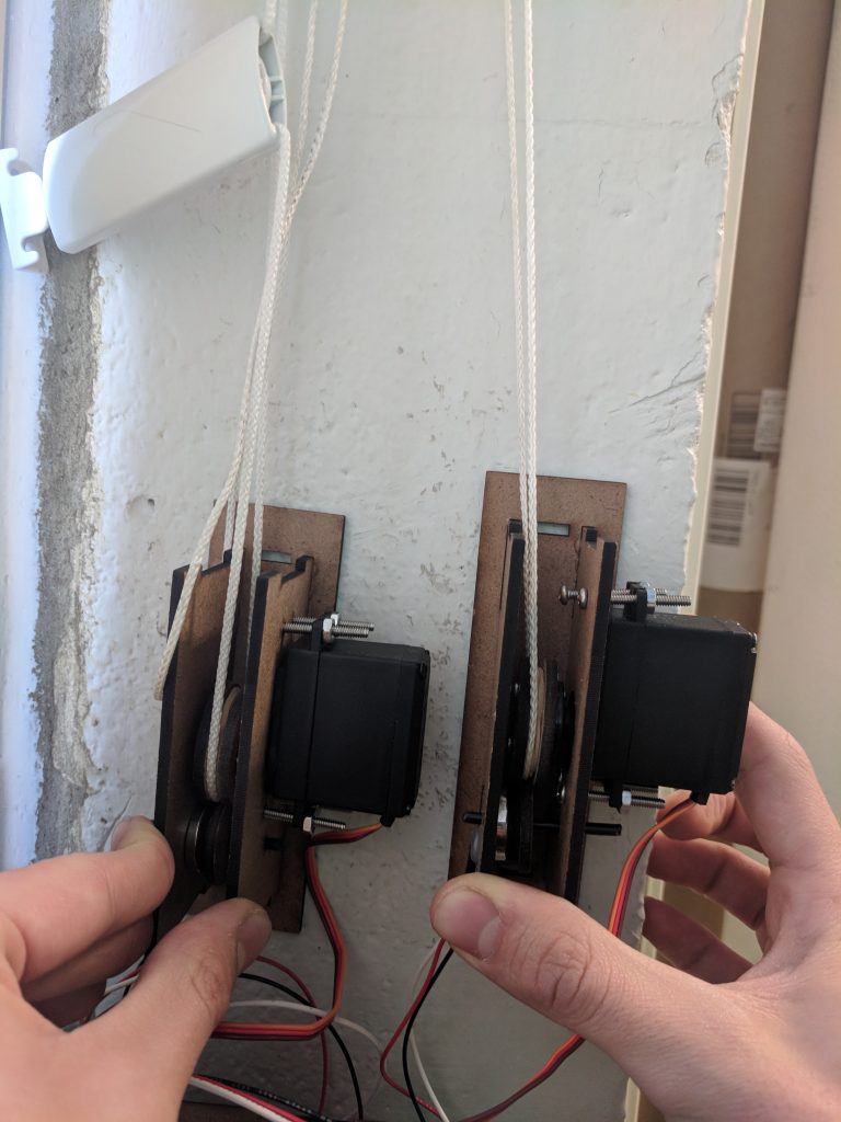
Fig. 2: Installed Drive Systems
Electronic Hardware
The circuit schematic for the light controller is shown in Fig. 3. The schematic for the shade controller is shown in Fig. 4. Both of these are fairly straightforward with few discrete components. The shade controller contains a voltage regulator for generating logic level voltages, an ESP, 4 buttons for manual control, and headers for the servos and Hall Effect sensors to attach. The Hall Effect sensors are used to detect when a pole of the multipole magnet passes by, therefore allowing the system to essentially use the magnet as a means of detecting “ticks” of rotation.
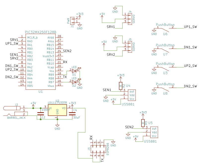
Fig. 3: Shade Controller Schematic
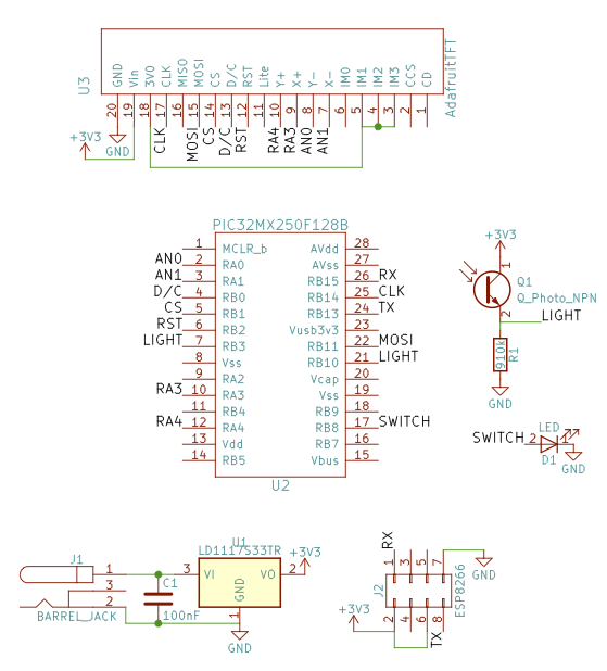
Fig. 4: Light Controller Schematic
Note that the light controller shows the use of a 3.3V regulator. For our testing, the 3.3V provided by the regulator on board the Microstick II was used.
For the shade controller, a PCB was designed and fabricated. The initial version had some errors, which were corrected manually with jumper wires. A rendering of the corrected version is shown in Fig. 5. The Gerber files for manufacturing can be dowloaded in .zip form here.
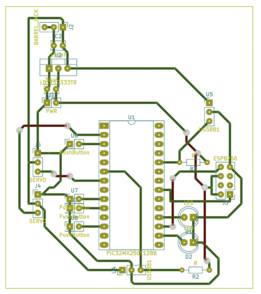
Fig. 5: Shade Controller PCB Rendering
Based off of the designs above, the software provided (Software), and the parts list (List of Parts), the implementation of the project can be recreated.
Obstacles Encountered
The mechanical shade drives had a tendency to be very finicky. Because we couldn’t permanently install them by drilling holes in the walls of Acopian, they had to be manually held, and their performance was quite dependent on the exact orientation at which they were held. Furthermore, a fair amount of testing had to be performed with various rubber bands and pulley sizes to balance pressure on the idler shaft and minimization of slippage.
The biggest problems, however, that were hardware related involved the shade control PCB. The ESP socket was originally laid out as a mirror image of how it should have been, and this meant that many traces had to be manually cut and jumper wire routed. Furthermore, some of the pads were really too small, given that the board was fabricated on a mill. Debugging all of the bad solder joints and shorts took quite a while.
Finally, our power supply exhibited very odd behavior. Sometimes there seemed to be either noise or a ground fault such that a motor would just decide to start rotating when not commanded. We were unable to find a consistent source for the problem for a very long time, and eventually discovered that the problem could be solved be using a bench supply instead of the wall transformer we had been using. We are not sure why this fix worked, but our best guess is that it involved too much noise on the power supply lines caused when the motors were spinning.