
Hardware
1. Real-Time Clock
As our system relied on events occurring at exact times throughout the day, we made use of the PIC32 internal Real Time Clock. The RTCC module used in conjunction with an external 32.768 kHz crystal were used to keep track of the time.
2. Servo Motor
For this project, we decided on the Servo Motor model TowerPro SG-5010 available on Adafruit. Functioning as the hardware end of food dispensing control, this motor requires at least a 4.8 V supply with a max of 6 V, and a PWM control signal. It can rotate in a range of about 180 degrees and can supply a torque of 5.5 kg-cm/76 oz-in at a 5 V supply, which is the supply that we ended up utilizing. For the control signal we used one of the PIC 32 Output Compare peripherals to supply a PWM signal with a 10 ms period routed through a logic level converter to turn the signal from a 3.3 V signal to a 5 V signal for the sake of the Servo Motor parameters.
Servo Motor Link: https://www.adafruit.com/product/155
3. Force Sensors
For our weight sensing element, we landed on the FSR 400 Series of Force Sensing resistors by InterLink Electronics, available on Mouser. Specifically we used the FSR 406 model, which is shaped like a square with an active sensing area of 39.6 mm x 39.6 mm. The sensor itself acts basically as a potentiometer, in other words a variable resistor which decreases in resistance when more force is applied to the active area. connected to our PIC 32 microstick in the configuration of a voltage divider. The sensor has two prongs, one attached to 3.3 V, the other connected to both a 10 K pull down resistor to limit to the current, and also to an ADC input pin of the PIC 32.
Force Sensor Link: https://www.mouser.com/Search/ProductDetail.aspx?qs=GURawfaeGuDaOmXus2Zwlg%3d%3d
4. Solenoid Valve
The issue of controlling the flow of water was solved when we found the Model 2W-160-15 Solenoid Valve available on Adafruit. A rather simple device which is default to closed which does not allow water to pass through, and opens with at least a power supply of 6 V and 1.6 A and a maximum of 12 V and 3 A. To ensure no issues with the operation, we decided on a mid level power supply of 9 V and 2.5 A. Along with the power source, additional circuitry is required to run a device of such a higher voltage than the signals of the PIC 32. Using an N-channel Power Transistor along with an optoisolator and some additional elements which can be observed in our system schematic, we can prevent any sort of inductive current spikes to the PIC 32 while still allowing us control of the valve from the PIC 32. The control signal from our microstick was a simple digital pin which was toggled between input (closed) and output (open).
Solenoid Valve Link: https://www.adafruit.com/product/996?gclid=CjwKCAiA9rjRBRAeEiwA2SV4ZUQeqYO1GsS_GUeuEHRmVT2telnghdiwEs7v6Q8UhzNS2Ph6uPc-dhoCPIkQAvD_BwE
5. Logic Level Converter
In order to properly control our Servo Motor, we needed to provide it with a control signal of at least 4.8 V and a max of 6 V. With the max output voltage of our PIC 32 being 3.3 V, we needed a way to step up the signal for the Servo Motor operation. For this purpose we found the 4-channel Bi-directional Logic Level Converter BSS138 available on Adafruit. When the lower voltage is applied to the LV pin and the higher voltage is applied to the HV pin, any logic signal can be applied to either side to receive the converted signal on the other side with the corresponding pin.
Logic Level Converter Link: https://www.adafruit.com/product/757
6. LCD Screen (GUI)
The LCD used in our project was the Adafruit 2.4″ TFT LCD. The LCD was used to display the user interface and its touch screen component allowed the user to interact with the system by setting the relevant information about the feeding schedule and meals. The LCD was configure in serial configuration rather than parallel configuration. Below are the various screens of the UI views.
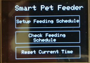
Main Screen
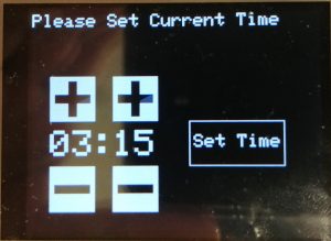
Setting Current Time
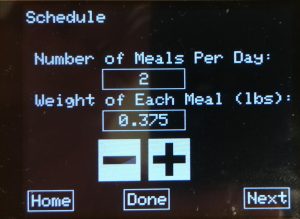
Setting Number of Meals and Weight Per Meal
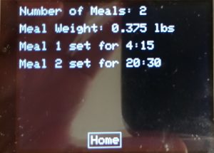
Displaying Set Schedule
Software
1. Program Structure
Our software structure is separated into three major elements: functions, protothreads, and interrupts, each controlling critical portions of the program logic. Our functions handle most of our preliminary program setup requirements and only run once per time the system is programmed. Our protothreads handle the functionality of our user interface elements, and the backbone of our timing triggering element. Finally, our interrupts handle most of the peripheral control and signal reception and interpretation.
We made two changes to the given existing touch screen code. In TouchScreen.h we changed the pins used for the touch screen functionality to allow use with the crystal oscillator. In TouchScreen.c we changed the code for setting the coordinates of the touch screen. Originally, the values were 100-900 for both the x and y coordiates. Our changes gaves us values of 0-319 in the x coordiante and 0-239 in the y coordinate.
2. Program Elements
i. Functions
Our software contains three functions: main(), initTimers(), and setRealTime(). The main function is responsible for configuring and initializing different aspects of the system such as initializing interrupts, clearing the interrupt flags, initializing the protothreads, initializing the LCD, and configuring the PPS and pin inputs and outputs. The main() function then calls the initTimers() and setRealTime() functions before going into the while(1) loop for the protothreads.
The initTimers() function is used to initialize the various timers and interrupts used throughout our system. Our system utilized Timer2 in 16-bit mode with a 1:8 prescaler, Timer3 in 16-bit mode with a 1:256 prescaler, and OpenCapture1.
The setRealTime() function is used to allow the user to set the time of the system. The system is called in the main() as the system needs the real time set to function properly. There is also an option on the main screen for the user to reset the real time. When this option is selected setRealTime() is called again.
ii. Protothreads
Protothreads were used extensively throughout our system as a way to handle the various user interactions. Protothreads existed for displaying the main screen, a screen to view the current feeding schedule, setting the current time, setting the number of meals and weight of each meal, and setting the feeding schedule.
Each protothread had a corresponding integer variable that acts as a boolean to control whether or not that protothread should be currently interacting with the system. After the while(1) of each thread, there would be an if statement checking if the variable was 1. If it was not, that thread would yield to the next thread without doing anything. If it was 1, then that thread would be able to carry out its functionality. For example, after the real time clock is set, the function sets drawMain to 1. This would allow the main screen thread to run fully. If the user selects the option to view the current feeding schedule, drawMain is set to 0 and drawFeedSched is set to 1, allowing the thread to print the current feeding schedule to the LCD.
iii. Interrupts
When it comes to our program timing elements, the main driver and support came from our system interrupts. Overall, we had two interrupts, each responsible for a significant chunk of our control and interpretation logic.
The first interrupt runs of a 16-bit timer with a 10 ms period. With the 10 ms period, this interrupt was based upon just the operation of the Servo Motor at first. The interrupt itself contains our conditional logic for controlling the Servo Motor when the pet needs to be fed and the food must be released into the bowl. By varying the value of the Output Compare’s OC1RS register we were able to properly step the motor to fit our purpose. Also within this first interrupt we can find the logic for controlling the water dispensing system. Along with various conditional elements which refine the control of this elements of the system, the actual control of the valve was form a digital pin which was toggled between input (closed) and output (open) with timing parameters which allowed for smooth operation.
The second interrupt also runs of a 16-bit timer but this time with a 100 ms period. A longer period was chosen for this interrupt because it contains mostly floating point calculation which can take a significant amount of the program memory so we didn’t want it to be running at a speed which could potentially slow the operation of our system. Based off preliminary testing, the logic of this interrupt reads the input from our force sensors routed through the internal ADC and calculates the most likely possible weight of the food and water and returns results within an interval of 0.125 lbs.
3. Difficulties
The reason we decided to not use exact values for the weight of the contents on the sensor was that through extensive testing, it was determined that the sensor is extremely sensitive to small changes in weight distribution. With the most accurate reading coming from a completely balanced food/water on the sensor. However the likelihood of a perfect balance occurring is very low, so a weight interval system was chosen instead.
We were unable to get the real time clock to trigger interrupts at the correct time. Ideally, the interrupts would trigger when it was time for a meal to dispense as set by the user. Due to these complications, we had to implement a protothread to act as the timer for the real time clock.