Week 4 Status Update

Goals:

  • Test the LoRa transmitter and receiver down by the river to see if it successfully transmits.(Austin/Matthew) – tested succesfully
  • Get data out of the data logger into the PIC.(Matthew)
  • Fix the issue with the extraneous characters when using RTCC alarm and sending from PIC to the LoRa transmitter.(Austin) – tested succesfully
  • Solder up a board with the PIC and LoRa transmitter and anything else.(Austin/Matthew)

Worked on:

  • Tested that the transmitter and receiver can transmit data from the data site to the public safety building. (Matt/Austin)
  • Fixed the issue with UART from PIC to the radio module and eliminated the extra characters. (Austin)
  • Figured out a way to read data from the receiver and get it put onto a folder onto the network. (Austin)
    • Accessed the information from another computer on the network (Matt)
  • Got both UART channels working alongside each other. (Matt/Austin)

Challenges:

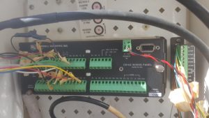
  • We have an issue with communicating with the data logger to get data out of it. We have seen the datalogger respond to a “ring” but we cannot establish a baud rate or get the data logger to send something to us.
    • The logger sets an output pin high to respond to us setting the ring pin high, which we verififed
    • Next step is to send carriage returns in UART spaced at least 50ms apart from each other at baud rate of 9600
    • Logger should respond by sending a *, but its TXD line is constantly low
    • We researched logic high in 5V UART and most systems count 2.6-2.7+ to be logic high. However could still be possible we need 5V logic to communicate

Week 3 Status Update

Goals:

  • Get PIC to utilize Adafruit Radio Module to send data
  • Set up PIC for sleep/idle mode with real time clock alarms for power conservation
  • Look more into ways to get data out of datalogger

Worked on:

  • PIC can utilize RTCC alarms to interrupt at a certain time rate (in our case it will be every hour.)(Austin)
  • PIC can use RTCC alarm to wake out of sleep mode.(Austin)
  • LoRa transmitter and receiver can successfully transmit and receive between each other.(Austin)
    • Range has been tested from the AEC 400 to the other end of acopian
  • PIC can send data through the LoRa transmitter. (There was an issue with this, more on it below.) (Austin)
  • Got the data logger into the lab to start working on getting the data out and tested signal response from the datalogger (Matthew)
  • Figured how to power the LoRa transmitter and PIC off of the data logger. (Matthew)
    • used 5V to 3.3V voltage regulator
    • If the logger is solar powered, than so will the PIC and the radios

Challenges:

  • There is an odd issue when using the RTCC alarm in the PIC when transmitting via UART to the Feather. The message contains the correct message and then a bunch of odd characters after. However, when not using the RTCC alarm interrupt the PIC will send the message just fine without any miscellaneous characters.
  • We’ve figured out the protocol for getting data out of the data logger, we just need to test and try to implement it.
    • We’ve gotten feedback from the datalogger when giving 5V to the “ring” pin

Next Week:

  • Test the LoRa transmitter and receiver down by the river to see if it successfully transmits.(Austin/Matthew)
  • Get data out of the data logger into the PIC.(Matthew)
  • Fix the issue with the extraneous characters when using RTCC alarm and sending from PIC to the LoRa transmitter.(Austin)
  • Solder up a board with the PIC and LoRa transmitter and anything else.(Austin/Matthew)

Week 2 Status Update

Goals:

  • Receive sample data from 9-pin output
  • Get parts in for system (radio transmitter, 5V to 3.3V converter)
  • Figure out how PIC can utilize RS232 to get data out of a 9 pin serial and eventually the datalogger

Worked on:

  • Set up radio module to begin interfacing with PIC
    • Adafruit LoRa radio transmitter programmed
  • Got parts in for system
  • Researched LoRa radio receiver techniques
  • Planning additional LoRa radio at receiving end to get data

Challenges:

  • Finding a way to get the various data out of the datalogger is tricky because the datalogger has a different pin setup and usually a program is used to access the data.
    • Also, it is unknown whether if we were to connect to the 9 pin setup what kind of data would exactly come out or if there needs to be some specific signal to get the datalogger data
    • 9-pin connector has ring buffer pin which seems to be used to interface with the data and begin transmission
    • Possible UART connection?
  • LoRa radio receiver with RTL-SDR requires several different packages to be downloaded and organized for an SDR

Next Week:

  • Get PIC to utilize Adafruit Radio Module to send data
    • Most likely SPI connection
  • Set up PIC for sleep/idle mode with real time clock alarms for power conservation
  • Look more into ways to get data out of datalogger
  • Determine which antennas to use for LoRa transmitter and receiver

Week 1 Status Update

Goals:

  • Research Potential Solutions
  • Get more information about the project from Professor Brandes
  • Plan high-level hardware and software design

Worked on:

  • Both – Talked to Professor Brandes to get more details. Visited the data logging site at the creek and took note of the current design.
  • Researched and found hardware components to purchase for our solution
  • Made a work schedule for each week of the project

Datalogger setup at the creek

Challenges:

  • Deciding on how to power up the micro controller when it is not connected to a computer
  • Planning software design for embedded system
  •  Narrowing down what items to purchase

Next Week:

  • Extensive research about utilizing our hardware equipment before they arrive
    • Radio transmitter from micro controller
    • Interfacing with datalogger
  • Receive sample data from 9-pin output
  • Put in parts order