Overview and physical connection:
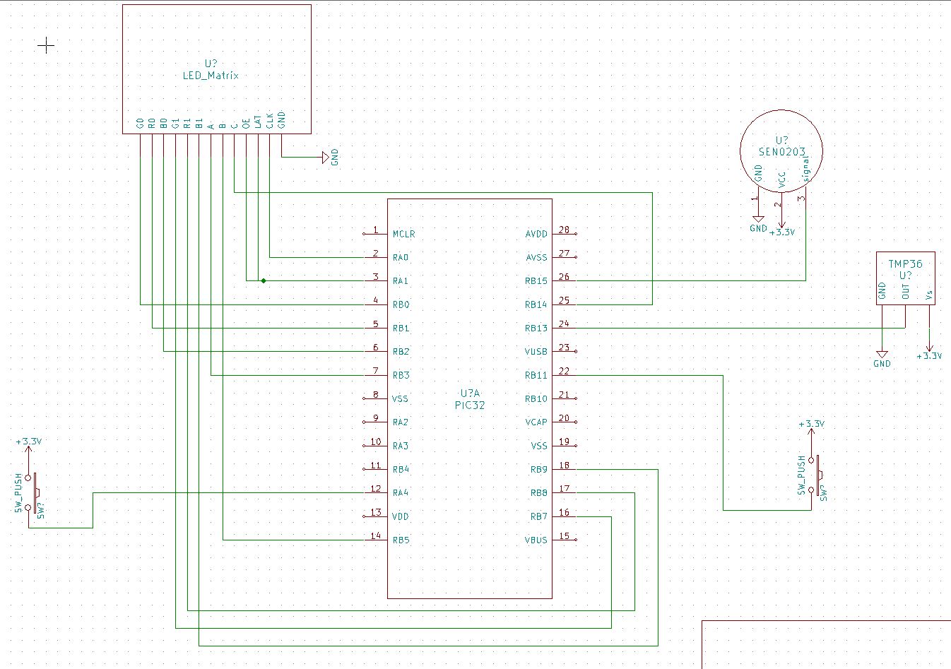
This is a pretty straight forward system which means it is pretty easy to recreate this system. One of the challenge is to set up the LED matrix because it has many connections. There are total of 16 pins for the LED matrix. For a 32×16 LED matrix, there are 6 RGB line (R0, G0, B0, R1, G1, B1), 3 row select line (A, B, C), 1 latch, 1 output enable, and 1 clock. (Reference: https://learn.adafruit.com/32×16-32×32-rgb-led-matrix/connecting-with-jumper-wires) The wiring choice for our project is shown in the system schematic below.
For other sensors, they were standard 3 pin connection (GND, Vcc, Output), just remember they do need to use ADC to convert the signal and make sure to wire the correct pins on your microcontroller.
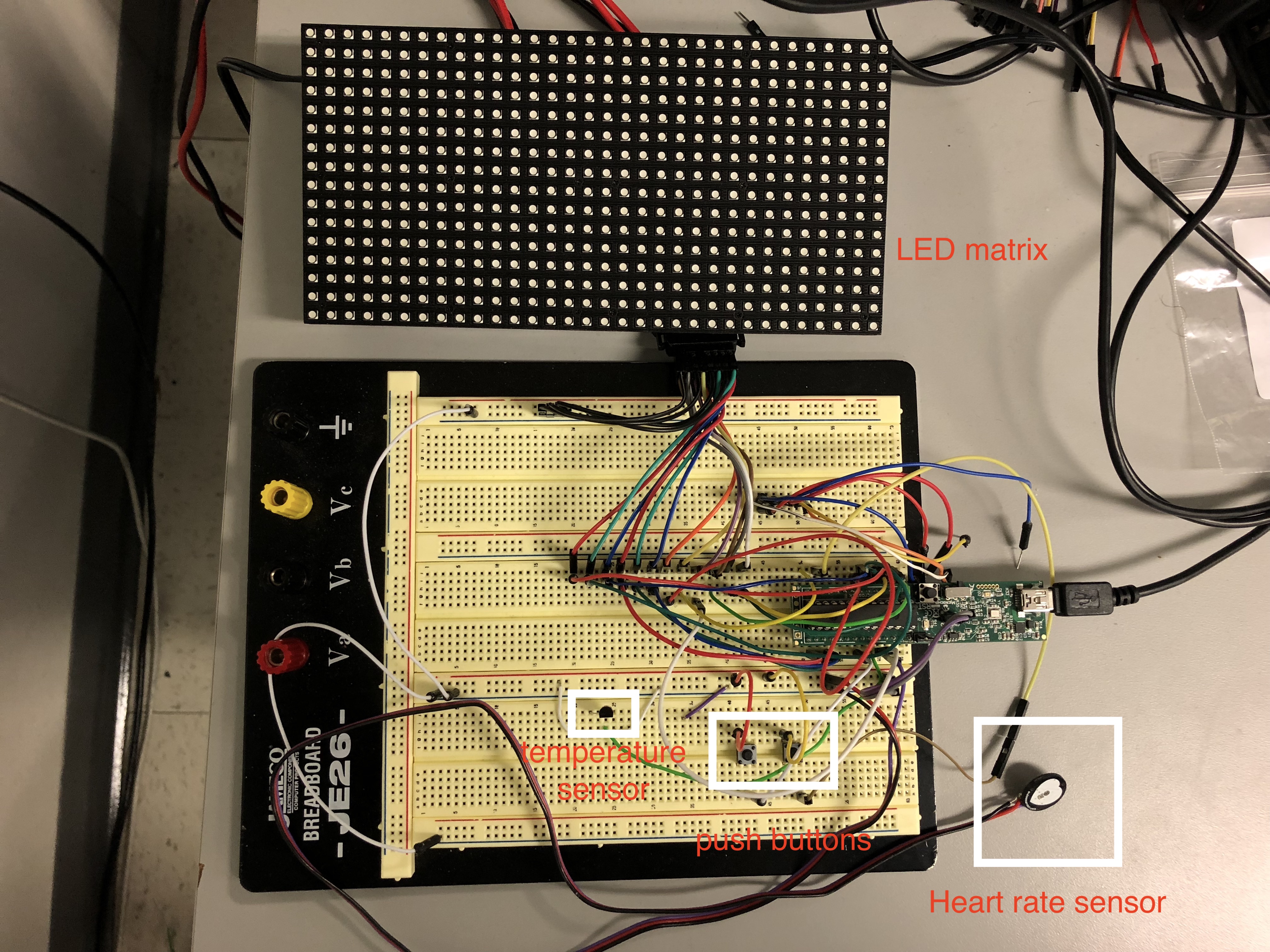
We also included our physical connection to show what is the physical layout of our design. Major components are highlighted.
System Schematic:
Physical Connection Image: