Software:
Below are the various key features of the software that the PIC32 is running. The software is divided into three different protothreads that all take care of individual components of data retrieval and transmission. There is an RTCC set up along with an ISR to interrupt every hour. The ISR is also used to wake up the PIC32 from sleep mode.
RTCC:
The Real Time Clock and Calendar (RTCC) is an important feature of the software. This allows the system to repeat it’s data retrieval and transmission every hour. It also is what will wake up the PIC32 from sleep mode. The RTCC is set up in chime mode to repeat every hour indefinitely (every 10 seconds for testing.) An ISR was set up along with the RTCC so every hour the interrupt would occur and wake up the PIC32 from sleep mode.
Sleep mode:
Due to concerns with power consumption on the current battery down at the data site, the PIC32 will be set up in sleep mode. Sleep mode will lower the power consumption by the PIC32. As was mentioned above the PIC32 will wake up from sleep mode by the interrupt from the RTCC. This increases the longevity of battery usage down at the data site. If Professor Brandes chooses to replace the lead acid battery with a solar panel, then the sleep mode will increase usage on extended cloudy periods.
Logger Protothread:
This was the protothread in charge of communicating to the data logger. The protothread would make the PIC32 emulate the protocol needed to get data out of the data logger. Some of the beginning behavior the PIC32 would have to do are things such as raising a “RING” line high, checking for the Modem Enable line to go high and then constantly sending carriage returns at 9600 baud rate. Once the RX protothread (explained below) received a ‘*’ from the logger, this thread is responsible for issuing commands to retrieve the data from the data logger.
RX Protothread:
This was the protothread that was in charge of looking at the data coming from the data logger and into the PIC32. This protothread is responsible in the beginning when the PIC32 would have to look for an asterisk in order to know that it could start sending commands to the data logger. It is also responsible for receiving the data from the logger via UART and storing it into buffers to later send (also via UART) to the radio in the radio protothread module
Radio Protothread:
This thread sends the data that the PIC32 has retrieved from the logger and store into buffers to the radio module via UART to then be transmitted over LoRa radio.
Hardware:
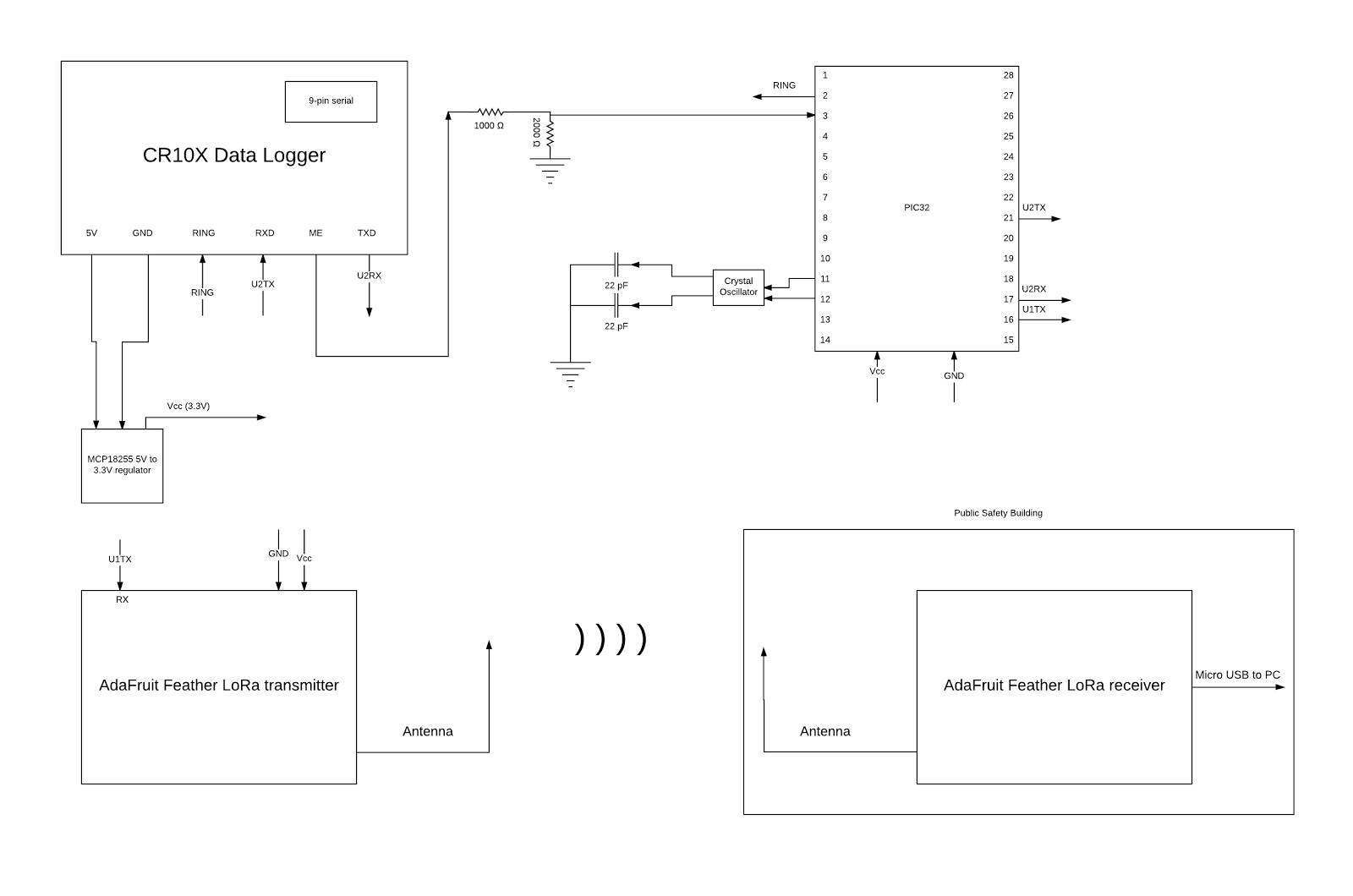
On the hardware side of things, it is straightforward and not very complex. Listed below are the various hardware components needed to make the system function as intended as well as a schematic of how the hardware was connected.
Crystal oscillator:
An external crystal oscillator was used along with two small capacitors in order to keep track of the time for the RTCC.
MCP18255:
This component is used to regulate the 5V from the data logger to 3.3V used by the PIC32 and the radio module. The radio module and the PIC32 are both supplied with 3.3V, so with this component we can safely power the PIC32 and radio module off of the data logger which uses the battery power.
Adafruit Feather 32u4 with LoRa Radio Module:
There are two of these modules used in the design. The first will be used as a transmitter and is hooked up via UART to the PIC32 to send out the data that is retrieved. The second will be used as a receiver at the Public Safety building and is hooked up to a computer that will run a script to grab the received data and put it into a CSV file.
CR10X:
This is the data logger that will be configured by the PIC32. The PIC32 will connect to various of the pins on the 9 pin serial in order to get power or data.
Schematic of Hardware Setup:
![]()
Difficulties:
The biggest problem that we have yet to solve in our system is being able to get data out of the data logger. This could be both a hardware issue and a software issue. On the hardware side of this problem we believe that possibly the 3.3V logic coming from the PIC32 into the data logger is not being registered or looked at correctly (as the data logger is 5V logic). However for the RING input pin we tested a 2.6V is enough to register it as logic high, which enables the ME line. On the software side we believe that there could be an issue with the way we are trying to send commands into the data logger. Moving forward we will potentially look into how the Campbell Scientific program sends signals into the data logger to get a clearer picture of the behavior we need to emulate.