Greetings, all!
Is this your first time using WordPress, or any other type of blogging software? Start here for some additional insight regarding how to use this site!
Greetings, all!
Is this your first time using WordPress, or any other type of blogging software? Start here for some additional insight regarding how to use this site!
Electronic instrument amplification may not seem like a complicated control system to anyone who has never used the equipment before, but to recording and performance artists, the tone of their sound is paramount. Ask any guitarist what the most important consideration is when selecting gear for their rig and they will almost unanimously answer: tone. So what determines this tone and how does the sound go from the weak guitar signal to the massive riffs that fill stadiums? The answer is amplification, electrical amplification to be exact. At a very high level, the pickups in a guitar translate the oscillations in the strings to an oscillating voltage (electrical signal) that is then fed into an amplifier or PA system. What makes amplifiers a special form of control system is that no one even thinks of them as a control system, once the guitar is plugged in, the sound is just automatically louder without any delay. This is the mark of a well executed control process.
Now, some lower level details about how exactly these amps boost the sound so well. The amp receives a power supply from the wall outlet and transforms a portion of that supply into a signal of a higher amplitude that matches the input signal. In the United States, this supply is an alternating current with a voltage of 120 V and oscillates at 60Hz with the amperage draw variant upon the appliance plugged into the wall. This is a standard supply and not in any way related to the signal the amp is attempting to process. This must be reduced and translated to a proportion of the full range signal the amp is capable of producing so that it does not damage the internal electronics which are not meant to handle household power.
Additionally, the gains that must be applied to the electrical power in the amp does not follow how we perceive the sound getting louder. While electrical power gains are linear, meaning that a gain of 3 will yield 3 times the output, gains that work with audible sound are logarithmic. When a volume knob is turned up on a stereo (an increase in the gain of the signal) and the sound appears to increase at the same rate, it actually increases faster at first and then slows down the more gain is applied. This means that the power increase needs to be related to the sonic output so that it gives the appearance of linearity and is easy to use.
Where amplification becomes significant from other control systems is in the tone, or the specific flavor of the sound and how it changes as it passes through the amplification system. Tone is essentially a modulation of the sound as it passes through the power transfer system. Many inexpensive amps use what is referred to as “solid state” amplification: using transistors and Op-Amps to increase the voltage and current of the signal from the instrument. They typically have a very clean, bland tone that can be very useful as a basic amplifier. Applications for these clean types of amplifiers include headphone amplifiers and small speaker amplifiers in computers, PA systems, keyboard amplifiers, and inexpensive instrument amps. They are not incredibly expensive to build, compact, durable, and accessible.
On the other hand, the most coveted amplifiers in history have all been tube powered. Using vacuum tubes as amplification circuits seems like antiquated technology in an age of touch screens and digital control but their sound is unparalleled. Artists like Stevie Ray Vaughan, Jimi Hendrix, Santana, and even contemporaries like John Mayer all play with these amps. But why?
It all comes back to tone. Looking at each of these individual types of amplification circuits, both perform the same function: taking a signal and making it louder. While neither of these are part of dreaded digital sampling, they do have very different characteristics that lead to different sounds and responses. Further work in controls will lead to a study in frequency response, which describes the differences quite well. Op amps are made up of transistors, arranged in such a way that they take reference voltages as the outer limits of their power and amplify the corresponding signal to within those bounds. Their responses are controlled and quick, but plain. Once the signal reaches the peak of what the circuit can produce, it maxes out the Op amp and it loses some of the character of the sound. This is known as saturation of the Op amps. Think of it as a transfer function that cuts out certain frequencies. For transistors, this filtering follows a first order frequency curve with no resonance. Simple and effective.
Tube amps use these “old school” vacuum tubes in the same way, but their response differs in that it does not behave as neatly. Ordinarily, this would be a problem, but its effect on the tone of the instruments is noticeably better. Its frequency response curve is more like that of a second order filter that has resonance near the cutoff. This resonance brings out frequencies and nuances in the signal that translate into what is referred to as great tone. Tube amps also have a unique feature where they do not saturate. Instead, they get overdriven, creating lovely bluesy sounds with a little bit of grit at harder playing levels while maintaining the clean tone at others. The level at which this “breaking up” occurs is controlled using the gain on the amp as well as the output level of the instrument.
As a control system, there is really not much to say. They are a very self contained system with the only outside control being the gain level and the level of the input. As such, the system itself is well designed and simple. Also, for such a system to have endured for so long; tube amplifiers have been around since the early 1900s, it stands as a solid testament to their quality and their effectiveness as a system.
They say the best things in life are the simplest, and few things speak truer to this than the quesadilla. At its purest form it is two heated tortillas full of melted cheese in the middle. The quesadilla originated in Mexico and can be modified to include a variety of meats and vegetables. But at the end of the day, you can’t beat the winning combination of cheese and bread. Quesadillas are commonly made using frying pans, but this method includes the obvious hassles of watching the quesadilla to make sure it doesn’t burn while also flipping it to cook both sides evenly. It was these predicaments that gave birth to the quesadilla maker. A quesadilla maker is essentially the cousin to the panini press: a machine that uses two heated plates to cook both sides of a sandwich. Panini presses have been modified into waffle makers and breakfast sandwich makers, but quesadilla makers are specifically designed with circular-shaped heating plates to perfectly fit tortillas.

Creating a Quesadilla Maker may seem simple in theory, but there are several variables that need to be accounted for. Anyone that has enjoyed a quesadilla knows that the biggest tragedy is finding out that your cheese didn’t fully melt while cooking. A close second tragedy is having a quesadilla that is too crunchy or burnt on the outside. This suggests that the variable that needs controlling in this process is the temperature of the heated plates of the quesadilla maker. Although this control is not necessarily essential to the device’s operation, avoiding both aforementioned tragedies would spare many a quesadilla lover a lot of heartache. So, we have the task at hand: we want to design a two-plated heating system that will both heat up the quesadilla high enough to melt the cheese fully, while not too high that will burn the tortillas. As time is of the essence for all quesadilla-lovers, we also must make sure that the quesadilla maker finishes in a timely fashion in order to have little wait time for cheesy-goodness. Our God-challenging machine will be fittingly named: the Queso-Roboto. While our task may seem impossible for some, we are chemical engineers. We live for the challenge, and more importantly, for the quesadilla.
According to Sargento, a global cheese superpower, cheddar cheese begins melting at approximately 66 oC. Cheddar cheese is undeniably one of the best cheeses for use in quesadillas, and is included in the recipes of many great chefs like superstar Paula Deen. We will use this melting temperature as the lower limit of our possible control range.

The upper limit of the possible temperature range is capped by the temperature at which the tortillas burn. Fun Fact: burning actually occurs when all of the water in a food has evaporated. This does not occur at a particular temperature, so an experiment to find the temperature that cooks the best quesadilla would have to be performed. This experiment would not only provide us with a set point for temperature, but it would also provide us with an ample amount of quesadillas. While some would burn during the experiment, we believe that a burnt quesadilla is better than no quesadilla.
In the experiment, our quesadilla research and development mavens would make quesadillas at temperatures increasing from 66 to 100 oC. Each trial would be run in triplicate to have an assessment of reproducibility, and panelists of a double blind study would rate the quesadillas. Rated attributes would be evenness of cooking, crispness of tortillas, cheese stretch length, perfect bite, overall beauty, Bue-No or Bue-Yes, and “wow” factor. The cook temperature determined to yield the most perfect quesadilla would be used as the set point temperature of our quesadilla making device. As with any self-respecting experiment, a randomized DOE run order will be developed. This will later be analyzed to note trends, reoccurring errors, outliers, and all the fixins.
A trial example and scoring is as follows-

In order to control the temperature of the plates, the variable that needs to be manipulated is the amount of current flowing into the quesadilla maker from the source of electricity. This can be practically done, by implementing a feedback loop that uses a temperature sensor to measure the temperature of the sizzling quesadilla, and compare it a set point. The controller will use any difference between the actual temperature and the experimentally determined set point to adjust the amount of current to either increase or decrease the temperature of the plates.
A possible disturbance hindering one from achieving quesadilla perfection is the fact that the press is not completely closed when it is operating. Because of this, heat is able to be exchanged with the air around the open edges of the press. Since the temperature of the air is cooler than the temperature of the inside of the quesadilla maker, heat is exchanged between the quesadilla and the ambient air. This creates a difference in temperature between the edges and the middle of the quesadilla. To account for this, the apparatus could be designed to have two separate heating mechanisms, and two different control systems. Each heater would have its own temperature sensor and set point, and would report back to its own controller. This would allow the temperature of the outside of the quesadilla maker to be slightly hotter than the inner temperature to allow for more even cooking despite heat exchange with the environment.
Another possible disturbance would be the blessing, and curse, of endless human creativity. The trials we are performing, consisting of purely tortillas and cheddar cheese, do no account for the free-thinkers and rebels of the quesadilla world. Our current model only works assuming that the quesadilla in question is in its most basic form. In world full of meats, vegetables, sauces, and guac, we will never be able to predict and prepare for every combination the Queso-Roboto will encounter. Instead, we will create a set time length and timer for the quesadilla models used in our trials, and leave it up to the discretion of the user to keep it in for longer periods of time. Though the insides will change, our original controller for the temperature limit and outside air effects should still be viable for these potential quesa-monstrosities.

Sources:
Cheese melting temp: http://www.sargentofoodservice.com/trends-innovation/cheese-melt-meter/
Paula Deen recipe: http://www.foodnetwork.com/recipes/paula-deen/cheese-quesadillas-recipe.html
Slightly over 30 years ago, we were promised by Marty McFly that by the year 2015, we would have hover-board and flying car. But unfortunately, McFly is a filthy liar and we still do not have either of these after one year. While we may not be able to fly around on our hot pink hover-board while donning the freshest of kicks any time in the near future, the advent of the driving cars will soon be upon us. There’s certainly no doubt that there’s pleasure to be found in driving, whether derived from a nice low grumbling of a V8 or simply flow the mechanical response with each input, but would it not be nice to take your hand off the wheel to watch a movie or catch up on emails instead of having to pay attention the soul crushing existential crisis that we call a traffic jam?

Jests aside, traffic related injuries account for a significant portion of unnatural fatalities each year. Despite the ever improved integrations of crash systems like the crumble zone and strategically placed air bags, the numbers remain disconcertingly high. In particular, these systems only aid to reduce the danger caused by the impact, but they do not contribute to the mitigation of accidents. In other words, previous advances in technology has solely been focused on a  passive reaction system and not an active one – and it is exactly therein lies the key to fully reducing number of traffic related injuries. There’s only so much that can be done to reduce the damage caused by a 2 ton truck broadsiding another vehicle – short of making the entire passenger compartment a reinforced sarcophagus (arguably more for convenience than safety).
For the longest time, active systems have not really been feasible as there has not been a push to wire a bunch of sensors up to a car. However, with the information age, comes too, the convenience of having sensors on all the things.  This opens up the opportunity of developing active systems in vehicles. The most useful of which will be, of course, for collision avoidance. No doubt that this would be by far the most important technology that needs to be developed before the first flying car, or whatever we choose to call it by then, could hit the sky. Partially because the cruising speed of these vehicles will be very high so a head on collision will probably have a delta V in the order of a Mach or so. Added to that, falling down another few thousand feet post collision will not aid the survival rate; that’s of course under the assumption that your entire everything won’t be vaporized in the collision, which is a pretty poor assumption to make.
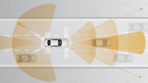
But back to the present day, what do we have at our disposals in these new generations of vehicles? In this example, we’ll use the Tesla Model S or the BMW S-class as they are some of the most well equipped cars. Here’s their sensor arsenal and let’s go through them:
Cameras: Pretty obvious one here. They are essentially like our eyes, so they’re pretty much useless in low light condition and needs time to focus on certain object in order to get a good image. Another down side of cameras is the fact that the raw data has no real intrinsic value and so they must be processed first before they are of any value at all to the system. Considering that in order to cover a full sphere of vision, the car will need to be installed with at least a dozen high definition camera. Considering the fact that we are trying to mitigate impacts, which mean that the system will have less than a second to response, this huge load straining on the system is not favourable. The upside is that an IR camera added such that problems with viewing in the dark can be more or less mitigated.
GPS: Again, familiar to all of us. This system has not much use since it usually has an accuracy of a few meters which is far too imprecise for our use in collision avoidance. That being said, the location data of the car can be used to determine how likely an event is to occur i.e. if it’s in a wood, then the system will immediately be on the lookout for deers/other animals crossing the road and if it’s in a large city, it will look out more for pedestrians.
Radar: This one’s obvious, more or less the ‘go to’ system to scan for objects and distance from vehicle. It has the downside of the fact that it cannot be used to identify the object or interpret the data in any other way than in manner that is similar to ‘there’s a thing this big over there and it is moving in that direction’. The fidelity of the data acquired by the system is also most likely fairly low as well
Ultrasonic sensors: This system has a range of circa 5 m, thus it is very useful in slow traffic or very dense areas. However, in fast moving scenarios, it is entirely useless.
As we can see, in the most advance of cars, there are more or less enough sensors equipped, or at least the types of sensors required for some level of autonomy. And of right now, a lot of them do have some sort of system to automatically break when a possibility of collision is detected. However, these are more or less relegated to the decision of breaking or not. It is essentially sensing the presence of objects as black boxes it should avoid instead of actually identifying the object.
To move closer towards a fully autonomous vehicle, the system must be able to distinguish between the different types of objects it may encounter, from animals to machines. As pedestrians are the biggest at-risk groups in traffic collisions, it is a wise choice to start with creating a system that could avoid pedestrians, even at relatively high velocities.
Traditionally, the process of object identification, situation analysis and resolution are divided into three separate processes. This is due naturally to the fact that there are so many factors that must be processed in each section. However, as we are simplifying the system significantly, they can all be grouped together and that’s what we’re going to do here.
Pedestrian Identification:
The pedestrian is first identified using a fairly complex but can be simplified down to being part of being compared to a probability mass function. Or rather, it is check whether a blob looks like a human or not.
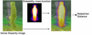
The measurement of distance between vehicle and object once the object is identified is fairly simple and does not require anything past pointing a Doppler radar/normal radar in that direction. At the same time, the velocity of each object can also be calculated based on the distance data and imaging data acquired. Tracked over a time interval of as few as three frames, the object’s velocity can be fairly easily calculated.
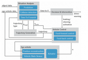
This information is then transferred onto the next stage where the situation is analysed, to assess for the time that is left until different event occurs, such as how long it would take to break, how long it would take to steer out of the way and finally how long it would take until collision.
This can naturally be broken into several parts:
Time to Break and Time to Collision:
These are obviously the most simple processes. As they are naught more than a basic physics calculation of how long it would take to come to a complete stop to avoid a collision or how long it will take on the current trajectory for the collision to occur. These are very basic physics calculation that anyone with a fundamental understanding of physics can easily calculate. They are also very simple to implement.
Time to steer:
The time it would take to steer in order to avoid collision with an object. This is far more complex as the system must not only calculate how long it would take for the car to steer around the object, it must also meet several constraints in that: the evasive maneuver must be feasible and the evasive maneuver must not result in a different collision. Additionally, as the driver would still be in primary control thus a fast yaw change should be avoided when possible to avoid the driver fighting the automatic maneuver which could throw additional difficulty into steering if ignoring driver interface is to be avoided. Unfortunately, due to the nature of human beings, the latter is not a possible option.
Automatic steering also includes a variety of concerns as well. One of them is that the system would have to, depending on circumstances, avoid multiple objects in succession. This would also lead to the scenario where a collision is certain to occur and the system must choose which target to hit (do you want to hit a kid at 20 mph or a family van at 50 mph?). This adds an incredible layer of unavoidable complexity into the system.
Once these parameters are calculated (and they are constantly calculated at the minimum time interval), they are passed on to the next function that will make the decision on how to intervene.
Decision and Intervention:
As the driver is still in control of the vehicle, first signals will be given to alert the driver of possible collision. If the time to collision and the time to break are equal to one another and the driver still has not responded then the system will automatically perform a breaking maneuver. However, if a breaking maneuver becomes impossible before the driver responded then the system will automatically make an automatic evasive maneuver in conjunction with cutting driver input during the duration of the evasion. Once the trajectory has been determined, it is passed on to the final part of the system.
Vehicle control:
This is essentially fairly simple and have been more or less been taken care of with the advent of technologies like traction control. In this step, the goal is to ensure that the vehicle follows the designated path. Similar to in the case of traction controls, the vehicle responses are completed at a hardware level using specifically designed chips.
As we can see, even though the process in a vehicle collision avoidance system can be very complex, the technology required to complete such tasks are on the verge of being standard in today’s vehicle. In particular, the fast hardware power that is required to process the variety of inputs into the system are more or less here (thank you Moore’s Law). Thus these systems are only years away from commonality. The biggest hurdles now will be the testing required to pass government standards. It is also here that a lot of problems still lie. From the point of view of the manufacturer, it is simply not good enough to simply reduce the number of vehicle collisions. The vehicle must perform the maneuver in a way that the company is protected from litigation. Think of it like this. If the vehicle has to choose between going on the course defined by the driver and hit a group of toddlers in the park, or it can take an evasive maneuver and hit a single person on the other side of the road, sometimes it may be better for the vehicle to just plow through the kids and put the blame on the driver. The alternative would be going into a costly court battle because it is technically the system that decided for the person on the other side of the road to get hurt. This is naturally, a whole different can of worms that we wish not to open.
What is an artificial heart?
An artificial heart is a prosthetic device that can take on the function of a human heart when necessary. The function of an artificial heart can be modeled as a process similar to those developed in chemical engineering applications. Several components of the human body serve as the process system that can be analysed when an artificial heart is used.
How does the natural human heart work?
Working to understand the various complex mechanisms and processes within the human body can potentially be useful in inciting innovation in biomedical fields. Because such systems are so intricate, it is necessary to pare down some of these and find ways to isolate them for individual study. It is also important to understand the functionality of the natural human heart, and how an artificial replacement works to mimic this functionality.
The natural human heart is controlled via a complex process involving a natural electrical system of sorts. The heart’s electrical system works to maintain a steady heart rate which varies to meet the body’s physical demand for oxygen at different levels of activity. With the help of conducting cells within the heart, which carry this electrical signal, and muscle cells, which allow for expansion and contraction of the heart, the heartbeat can be controlled.
Other processes within the human body also work to control the heartbeat. The brain, for instance, is integral in sending signals to the heart when a faster or slower heartbeat is necessary. The brain essentially works to control the initial electrical signal to the heart, which is fired off by the heart’s sinoatrial node. Hormones (i.e. adrenaline) and several components of the nervous system can also have a key impact in how the human body works to alter heart rate.
Approaching the design: how can an optimal artificial heart be developed?
The purpose of this journal is to design and study an artificial mechanical heart that can physically replace the natural human heart. Over the course of the past few years, both external and internal artificial hearts have been developed for people who have suffered chronic heart failure and have been ineligible for a total heart transplant. However, many of these artificial hearts, especially the earliest prototypes, have almost never been implanted successfully. Most prototypes have worked to produce a constant flow of blood throughout the human body. Only very recently have scientists began to develop more complicated control systems that change the output blood flow rate based on an increase in human activity (i.e. during periods of exercise). The design proposed in this journal works to control the oxygen concentration within blood by manipulating the blood flow rate and respiration rate.
Both an optimal material design and vigorous process control mechanism need to be considered in the development of the artificial heart proposed. Biocompatible materials are essential when designing a device to be implanted into the human body. In early artificial heart designs, plastic compounds and titanium were often used. In more recent design efforts, scientists have begun to incorporate biological components, i.e. valves made from chemically treated animal tissues.
Why does it need control?
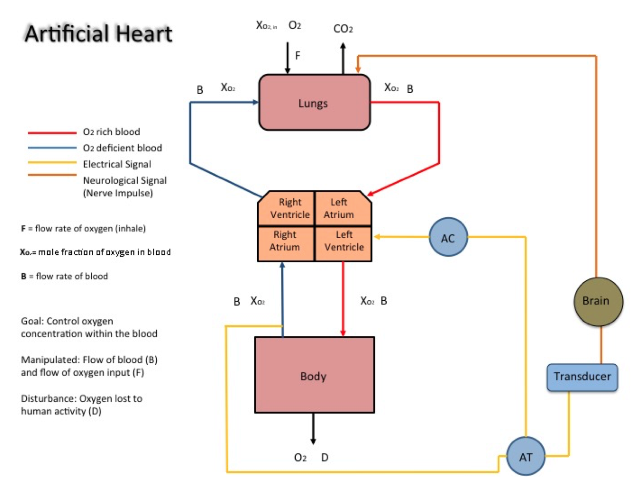
In terms of process control, an artificial heart can serve to regulate the average oxygen concentration within the body. Depending on the user’s level of activity, physical condition, or human mass, the control system will help to manipulate the volumetric flow rate of blood being pumped throughout the body and the level of rate of oxygen intake. Signals are sent to the mechanical heart and to the brain in order to control these variables.
Maintaining the oxygen concentration in the blood within the body is vital to support human life. Nearly all of the body’s activities, from brain function to elimination, are regulated by oxygen. Oxidation is the essential factor for metabolic function, digestion, and circulation. Thus the proposed mechanical heart must be able to efficiently pump flow through the body, as well as be able to be manipulated by the controller to maintain healthy blood oxygen levels. Heart disease is considered a major health problem internationally. Fabricating a mechanical heart will allow people to live longer lives and maintain increased levels of activity.
The major protein that aids in the transport of oxygen in the blood is hemoglobin. In normal arteries, hemoglobin is about 97% saturated with oxygen. There are about 15 grams of hemoglobin per 100 mL of blood. Each gram of hemoglobin can bind to 1.34 mL of oxygen. Thus, the normal concentration of oxygen in arterial blood is 2.45*10^(-4) g/mL. According to the American Journal of Cardiology, blood concentration below 90% (or 2.27*10^(-4) g/mL) is considered to be potentially dangerous and is thus the lower limit of this operation.
How it works.
A concentration sensor-transmitter measures the remaining concentration of oxygen within blood after the blood cells deposit the oxygen throughout the body. This transmitter is located right before the right atrium in which the oxygen-depleted blood enters. The electrical signal is sent to two locations. First, it is sent to the proposed mechanical controller, which changes the speed of the artificial heartbeat via a pump. This action manipulates the flow of blood, thus controlling the amount of oxygen that can be delivered to the body. Additionally, the electrical signal is sent to a novel transducer, in which the signal can be transformed into a neurological impulse that is sent to the brain. The brain functions as a natural control system that changes the breathing pattern in the lungs. This manipulates the flow rate of air, thereby controlling the oxygen concentration within the blood.
The measured control variable, the oxygen concentration, changes upon disturbances such as an increased or decreased level of activity. The feedback process described above works eliminate rapid changes in oxygen concentration and to approach a set point.
One potential disturbance variable to consider in this process system is variation in human activity. Increased physical activity, such as cardiovascular exercise, will result in depletion of oxygen within the blood. The change in oxygen saturation will cause a deviation from the set point and theoretically, a feedback loop should cause the mechanical heart to pump at a faster rate to achieve the set point.
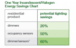
Artificial light is an integral part of life. Without it, daily functions would be restricted to the hours of natural light provided by the sun. With 24-hour access to artificial light, the workday can turn into the “work night.” Although artificial light is extremely beneficial, it also has its downfalls. One main disadvantage is the vast amounts of energy consumption. Even though artificial light is needed, not every circumstance calls for blinding amounts of light when there is perfectly good natural light right outside the window. However, many artificial lights only have one setting which leads to two options: total darkness or full on blinding light. This can lead to a huge waste of energy. Flipping a light switch or walking down a well-lit hallway are both everyday luxuries that are often taken for granted. The easy access of artificial light has resulted in abuse of it as a resource. Figure 1 shows the potential savings by using dimmers.
This energy could be conserved if there was a system that measured the amount of light present and then only supplied enough artificial light that is needed. For example, imagine if during the peak hours of sunlight, artificial lights would dim automatically to adjust for an increase in sunlight. This would decrease the amount of energy use and, ultimately, save money. As the sun begins to set, the artificial lights in a room would compensate for the loss of natural light to keep a constant and desired amount of light in a room. The idea of auto dimming has many benefits other than saving energy and money, like extending the life of a light bulb, creating a more productive atmosphere, and a healthier life in general.
The reason why this product is so valuable is that it can reinvent the way people not only light their homes, but also office buildings, schools, and other public spaces. In public spaces, people don’t usually pay much attention to the status of the lights and often forget to turn them off when they leave a room. Along with over use of artificial light when people are in the room, there is even more wasted energy of when people leave lights on in an empty room. This product will not only have auto dimming but also a controller that can dictate when lights should turn off and on at the beginning and end of a work day.
This auto dimming lighting system uses a sensor that detects the brightness in a room, which then transmit a signal to the artificial light, which also has a sensor attached to it. The sensor will then tell the controller to dim or brighten the artificial light according to the amount of natural light already present in the room. For example, at night the amount of artificial light will be the highest level since there is no sunlight available. As the sun starts to rise, the amount of artificial light starts to decrease since the amount of light already present starts to increase due to the increase of sunlight. Unlike a timer system which would just have the amount of artificial light increasing and then decreasing with respect to time, a process controller would also allow for the total amount of light to stay constant even on cloudy days. A similar control process is used in devices such as IPhone and IPad in order to adjust the brightness of the screen in response to the lighting of the surrounding environment.
The controlled variable is the amount of light in the room. To determine the ranges of this variable, the consumer would do a calibration based on their preference of what the desired amount of light in the room should be. This would include light in the early morning, mid-morning, midday afternoon, evening and night. The control of this variable is crucial to the operation of this product because if the light is not controlled, the dimmer will not work properly and provide adequate amounts of light. However, since lights can be controlled manually by a person flipping a switch, controlling the amount of light is not crucial to the original function of the light.
The manipulated variable of this process is the amount of artificial light in the room. However, it would only be the overhead artificial light sources. Other sources of artificial light, like floor lamps, flashlights, and desk lamp would not be considered manipulated variables because they are used for additional light needed for specific locations. These would be considered disturbance variables since when a lamp is turned on, the ceiling lights or recessed lighting would adjust based on the amount of light in the room. Other disturbance variables are the amount of light coming into the room and where it shines. For example, if curtains are suddenly closed, the system needs to respond quickly so that the person in the room is not left in the dark. It is more practical for the artificial light to be the manipulated variable than the sunlight since it would be harder to control the amount of sunlight coming into the room with curtains or mirrors.
These disturbance variables would all be controlled by the same manipulated variable, the amount of artificial light, by way of a feedback loop. A feedback loop is when the output of the system is compared to a known or ideal value. The difference between the desired amount of light and the actual amount of light in the room is then turned into an error signal that is transmitted to a controller. The controller would then adjust the amount of artificial light supplied to the room based on this error. Figure 2 shows how all the variables interact.

Installing this controller is better for the environment and the user’s wallet because it ensures the minimum amount of electricity, and thus energy, is used throughout the day. The video below demonstrates how the auto dimming lights can be used in daily life. As the curtain rises, the artificial light in the room begins to dim. However, the total light in the room remains the same. Thousands of watts of energy are unnecessarily wasted because the availability of natural light that is neglected. And God said let there be light, NATURAL light. So use it, dang it!
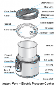
When boiling, baking, frying, roasting, stewing and steaming can be performed by a single cooker, would that be your “one-for-all” weapon in kitchen? A multi-cooker makes your dream come true! The multi-cooker, often seen in Asian and European kitchens, has significantly improved the quality and efficiency of cooking. As an advanced combination of the slow cooker and the pressure cooker, the multi-cooker became more and more popular in modern kitchens. This article describes how a multi-cooker works and explains the details of the internal control system. A multi-cooker controls the temperature and pressure inside the cooker by manipulate the heat flow rate and amount of steam in the cooker in order to properly cook the food. The most fascinating thing about multi-cooker is that it has multiple embedded functions that can be applied to different types of food by simply clicking on these functional bottoms.
Allow commercial talks about how good it is:
Pressure and temperature of multi-cooker are controlled variables that are significant in this control process. Depending on the property of food (i.e. texture, liquid content and solid content) and the cooking style, setpoints of temperature and pressure under which condition the food can be properly cooked will be experimentally determined. A multi-cooker usually uses a negative feedback loop where temperature and pressure of the cooker can be adjusted to reach setpoints. Typically, the temperature and pressure sensors measure the temperature and pressure in the cooker, and compare measured values with the set points. Then a controller will make decision and take action to adjust the temperature and pressure to approach their setpoints. In order to speed up cooking process, maintain the original flavors of food, it’s important to keep the cooker pressure and temperature in a reasonable range or at a specific value to ensure the cooker working at a relatively high efficiency and avoid potential safety issues.

In order to minimize the difference between cooker temperature and the set point, it’s necessary to adjust the other term called manipulated variables, which are controlled by the controller mentioned above. In the multicooker, the manipulated variables are temperature and pressure of the cooker.
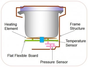
To control the temperature of the cooker, heat flow rate is one of the main manipulated variables which varies in order to minimize the difference between cooker temperature and the set point. As mentioned, the manipulation of heat flow rate by the cooker itself can be achieved by a feedback response provided from a temperature sensor in the cooker. For instance, the best temperature of cooking steak is about 140 degree Fahrenheit, the moisture inside the steak was heated from room temperature to a higher temperature. At the beginning, the heat flow rate transferred in by a thermal panel will be much higher compared to middle or final stage of cooking. Later in the process, the temperature of steak will not be higher than the set point (140 degree Fahrenheit) ideally. Such adjustment can be done by a controller, which in this case, would be a thermal converter that converts electricity to heat. Specifically, An adjustable resistor in a circuit board then manipulates the heat flow rate in order to change the temperature of cooker.

On the other hand, the manipulated variable for the pressure in a cooker is the amount of steam. The pressure of the cooker usually reaches as high as 2 bars. Making the boiling point of liquid (usually water, sometimes wine or broth) in the pot higher than its normal boiling point at atmospheric pressure. A rise of pressure lets the food inside the pot to be cooked at a higher temperature thus the time needed for cooking has shorten by a large amount. This characteristic function is borrowed from pressure cooker where the food will not be smashed because the pressure formed by steam that applies pressure uniformly across the entire cooker. As long as there is some amount of liquid in the cooker, steam can be generated by the heat provided. In order to control this process, a fail-close (ATO) valve works as a controller to automatically adjust the amount of steam in the pot in order to control the cooker pressure. For example, when the pressure inside the cooker is too high compare to its setpoint value, the sensor then will let the valve to be open in order to release some steam.
However, there are some other factors, known as disturbance variables, which may disturb the control system. Disturbance variables have effects on the controlled variables but they cannot be manipulated in the process. In the multi-cooker, the potential disturbances are heat or gas leak from the cooker and disruption of electric current.
Ideally, the current supplied to a multi-cooker is stable and constant. As a result, the cooker can have a stable rate to transfer electrical energy into heat in order to allow its internal system to calculate how much time is needed to achieve the set point. In this case, any changes or disruption on the electric current can negatively affect the efficiency of the cooker and disturb the system. For example, if the amount of electric energy supplied into the cooker is less than the steady state value, it will make multi-cooker to take longer to achieve the desired temperature and pressure. The heat or steam leak from the cooker is also unpredictable and hard to control. Usually designers will try to avoid the leaks, but the possibility of leaks is still present when a cooker has been worked for a long time and some components failed to function properly. Other disturbances include the adjustment on the desired temperature or pressure, known as controlled disturbance. As we change the set points, the time for heating or pressurizing will be changed accordingly. It’s recommended to determine the desired temperature and pressure, which are corresponding to different programs embedded in the multi-cooker before the it starts to work to avoid the controlled disturbance.
Furthermore, the time which takes the cooker to adjust temperature from initial values to setpoints, there is a further time period needed for cook food thoroughly. Such period is set as well as a timer that allows people to see how long it takes for the food to be ready. The length of this period depends on the category of food just like how the temperature and pressure set by experiments. During this period, the cooker will theoretically keep running at the same temperature and pressure. However, the temperature and pressure might be unstable thus same controllers will be working in order to cover the difference.
As an independent household appliance, a multi-cooker saves your money, time and space compared to old styles cooking equipment: all kinds of pans, steamer, slow cooker and oven. Multi-cooker, a universal solution which can replace all of the above appliances, it can even be a fryer when you leave the lid open. Especially, when compared to a slow cooker which cooks food slowly and at low temperatures, it mainly takes you several hours to cook meat in the slow cooker that is an unimaginable luxury for a modern person! The Multi Cooker, in the contrary, cooks twice as fast than a stove. It concerns even the most complicated dishes which require long thermal processing. Also the slow cooker is not recommended for food reheating while it is quick and easy to do so by a multi-cooker.

The feedback-loop multi-cooker owns, enhances its advantage even more, compared to a pressure cooker which can only adjusted by turning on/off stove, has a more advanced adjusting system as a more automatic appliance since temperature and pressure are controlled. Manipulated variables like heat flow rate and amount of steam altered by controllers (resistor and valve), also help the cooker for making delicious cuisine. If there is anything else that can be improvement based on the current model, safety should be considered. A pressure release valve might be involved when electric current suddenly drops to prevent a rapid decrease in pressure. But overall, multi-cooker will be a powerful tool in your kitchen.
Leaving lights on at full blast for all hours of the night can be wasteful, especially when there are no people around to benefit from that light. Energy is wasted, and checkbooks run thin when it is time to pay the bills. Our idea is to design a system of motion sensor lights that also have a dimming function based on sensed light. The motivations of examining this process are energy and cost reduction. Both can be saved by using automated lights that turn off when there is a lack of movement or where there is enough ambient light.
The controlled variable of this system would be the level of light given off by the light bulb. This variable is manipulated by the change in energy supplied to the bulb. The operating range would be determined by the level of light detected by the light sensor. The system would operate off of two main ranges of operation. The “good” range of operation would be the range in which there is enough natural light, such as during the daytime or when nearby lights are illuminated enough. In this case, a signal would be sent by the sensor to turn off the bulb. The system would turn on upon reaching the “bad” range of operation, in which not enough natural light is present for proper sight. A signal would be sent by the sensor to the controller, causing the bulb to apply light.
While the dimming and motion activating functions are the cornerstones of the system, they would not be necessary to act in the bare-bones functions of a conventional light. Fortunately, in the event of a malfunction, not all functionality would be lost. Therefore, the product would still function as a light without the necessary adjustment of light level. The light level sensor control is an improvement because it saves energy on lights when the energy applied is not necessary. During daylight, it is more efficient for the light to be off. The motion sensor control is an improvement because it makes living alone more manageable. If a person came home from grocery shopping late at night, the automated light sensors would turn on at his porch and in his house as soon as he is within a certain distance.
The motion sensor is another benefit to the operation of the light function. It is supportive of the user experience due to the convenience of an automatic versus manual control. If there is no error reading in the light sensor, the motion sensor does not respond to motion because there is already enough light present. Motion control creates a safer environment such as in parking lots or along sidewalks among other public places. Furthermore, this product is cost effective, since less power is used up by the light bulb than if the lights were on for the whole day.
The manipulated variable is the energy applied, which can have numerous points of manipulation, such as for a daytime and nighttime setting. Once the surroundings reach a certain level of brightness without movement, the system can shut off completely. For examples, after 5 minutes of inactivity or sufficient lights for 5 minutes. At this point, there would be no electricity applied to the light bulb, but there would still be electricity flowing through the sensor so that it could allow for a quick response through the controller. During a lack of motion, energy would be saved due to the light bulb being off.
Because of the presence of two sensors, potential disturbances in either sensor could affect the output. Light level disturbances may include the headlights of nearby cars or lights from television or computer screens. Motion disturbances, like the small movements of bugs flying around the sensor could also have effects. In addition, the sensor would need to ignore the effects of inclement weather, such as rain or snow.
To mitigate these disturbances, a PI controller should be used. A derivative response would be too erratic for the potentially noisy data received by the sensors. The infrared motion sensor, designed to detect high levels of infrared radiation, could be set to only send a signal for detected heat sources of greater than 90°F. Requiring these sources to be localized would avoid issues arising from a summer day when it is above 90°F outside.

Figure 1: Infrared Motion Sensor
The variables of light level and motion disturbances would both be controlled by the manipulation of energy. A sudden detection of motion would require a quick response of energy from the controller while a sudden change in light would require a slow or delayed response. As a person approaches a motion sensor controlled light in a parking garage, it is important that the light illuminate. A slow response in this case would not do much for safety. On the other hand, light disturbances from passing headlights do not need to be addressed by this light system. Changes in light level typically happen over a long time, so a slow response would be acceptable.
The process would be controlled via a third order feedback loop while the motion sensor would contribute a simple unit step to the controller. The following block diagram represents the light and motion sensor system. Xdl and Xdm represent the light and motion disturbances respectively. Gdl and Gdm represent the transfer function of the light and motion disturbances. Xspl and Xspm represent the set points for light and motion. With this block diagram, the system would be developed and the product would be possible. No more useless energy consumption!
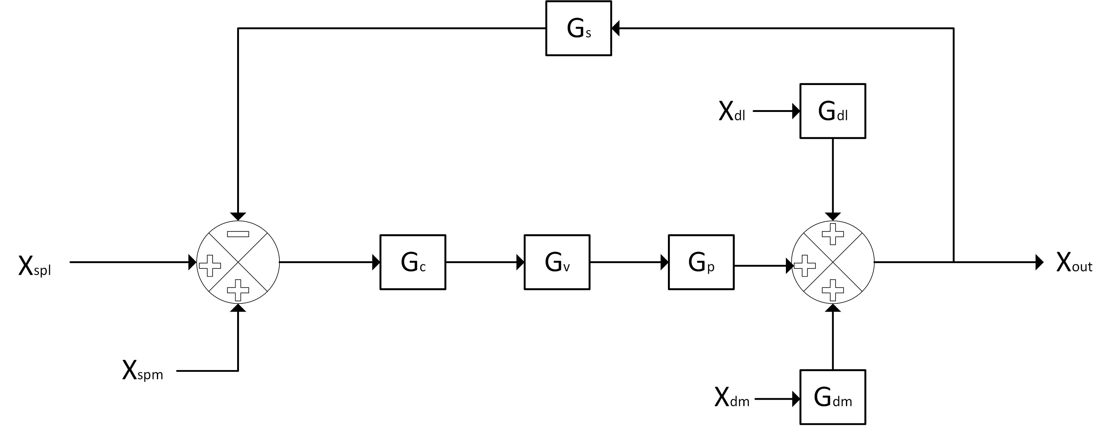
Figure 2: Block Diagram
Reference:
With spring break right around the corner, we and our classmates will be boarding planes, crossing state lines, and traversing the globe in order to have the best #SB2K16 we so desperately need. Some of us will be traveling to other continents, going home or seeing friends abroad, while others will be traveling to a tropical place to catch some rays. What we all have in common though, is that we will all be kicking off our spring breaks by going through security, getting side-eyed by the TSA, boarding a plane and taking our seats (probably a middle seat lets be honest). Once we take off we’ll probably take out our phones and put some music on and try to go to sleep since our flight boarded so early. What we won’t think about though is how our plane is going to stay safe throughout our flight and allow us to breathe as we soar thousands of feet above land and sea.

All planes are equipped with an environmental control system (ECS) that provides air supply, thermal control and cabin pressurization for the crew and passengers. The ECS is operated through a feedback system, therefore cabin pressurization and airflow is monitored and the air intake from the outside is adjusted accordingly. On aircrafts, air is supplied to the environmental control system by being “bled” from the compressor stage of a gas turbine engine. The temperature and pressure of the “bled” air varies depending on which stage of the compressor it is coming from, and the power setting that the engine is operating. 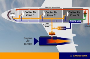 To control cabin pressure, air conditioned air from the ECS is pumped into the cabin of a plane to create a safe and comfortable environment for passengers and crew flying at high altitudes. The air supplied to the fuselage is cooled, humidified, and mixed with recirculated air before it is distributed to the cabin. Pressurization is necessary at altitudes above 12,500 to 14,000 feet above sea level to protect passengers and crew from health problems caused by the low outside air pressure above those altitudes but is a requirement for cruising altitudes above 8,000 feet.
On the ground, the airplane is unpressurized and the outflow valve is wide open. During preflight, the pilot sets the cruise altitude on a cabin pressure controller. As soon as the weight is off the main wheels at takeoff, the outflow valve begins to close and the cabin starts to pressurize. The airplane may be climbing at thousands of feet per minute, but inside the cabin, the rate of “climb: is approximately what you might experience driving up a hill. It might take an average airliner about 20 minutes to reach a cruise altitude of approximately 35,000 feet, at which point the pressurization system maintains the cabin at the pressure you’d experience at 7,000 feet: about 11 pounds per square inch. Of course our ears may pop, however, the effect is mild because the rate of the climb is only about 350 feet per minute. When the airplane descends, the pilot sets the system controller to the altitude of the destination airport, and the process works in reverse.
The structural strength of the airplane determines how much differential pressure the cabin can tolerate—a typical figure is eight pounds per square inch—and the fuselages of new airplane designs are pressurized and depressurized many thousands of times during testing to ensure their integrity.  The higher the maximum differential pressure, the closer to sea level the system can maintain the cabin. Federal Aviation Regulations say that without pressurization, pilots begin to need oxygen when they fly above 12,500 feet for more than 30 minutes, and passengers have to use it continuously above 15,000.
The structural strength of the airplane determines how much pressure the cabin can tolerate, a typical amount is about eight pounds per square inch, and the fuselages of new airplane designs are pressurized and depressurized many thousands of times during testing in order to ensure their integrity. Planes are designed so that occupants will not be exposed to altitudes over 25,000 feet for more than 2 minutes or at an altitude of 40,000 feet at any time. These regulations are in place in case of sudden decompression.
Pressurization is achieved by the design of an airtight fuselage engineered to be pressurized with a source of compressed air and controlled by an ecs. Air enters the system as bleed air which is extracted from the compressor stage of a gas turbine engine at a low stage and from an additional high stage. By the time the cold outside air has reached the bleed air valves, it is at a very high pressure and has been heated to about 200C. The control and selection of high or low bleed air sources is automatic and is governed by the requirements of various stages of flight. The part of the bleed air that is directed to the ecs is expanded and cooled to a suitable temperature by passing it though a heat exchanger and an air cycle machine called the packs system. At least 2 different engines provide the compressed bleed air for the plane’s ecs. Exhaust air is pumped into the atmosphere is an outflow valve, usually at the rear of the fuselage. This valve controls the cabin pressure and also acts as a safety relief valve. Is the automatic pressure controllers fail, the pilot can manually control the cabin pressure valve and the plane can still fly smoothly. The automatic controller normally maintains the proper cabin altitude by constantly adjusting the outflow valve position such that the cabin altitude pressure remains as low as possible without exceeding the limits of the fuselage.
Unplanned loss of cabin pressure at altitude is rare but has resulted in a number of fatal accidents. Failures range from sudden, catastrophic loss of airframe integrity, known as explosive decompression, to slow leaks or equipment malfunctions, that allow cabin pressure to drop undetected to levels that can lead to unconsciousness or severe performance degradation of the aircrew.
Any failure of cabin pressurization above 10,000 feet requires an emergency descent to approximately 8,000 feet or the closest to that while maintaining the Minimum Safe Altitude (MSA), and the deployment of an oxygen mask for each seat. The oxygen systems have sufficient oxygen for all on board and give the pilots adequate time to descend to below 8,000 ft. Without emergency oxygen, hypoxia may lead to loss of consciousness and a subsequent loss of control of the aircraft, since the time of useful consciousness varies according to altitude. As the pressure falls, the cabin air temperature may also plummet to the ambient outside temperature with a danger of hypothermia or frostbite. In jet fighter aircraft, the small size of the cockpit means that any decompression will be very rapid and would not allow the pilot time to put on an oxygen mask. Therefore, fighter jet pilots and aircrew are required to wear oxygen masks at all times.
So, the next time you’re on a flight and you’re thinking, “How the heck am I breathing right now?”, just refer to “The Mile High Club”, for everything you need to know about cabin pressure during air travel.  Once you read it you’ll start to realize that it’s a very complicated process you may never fully understand, nor do you really want to because who wants to be paranoid about cabin pressure for a whole flight? As long as your pilot shows up sober, you should be fine!
Do you often find yourself wondering just how much detergent you should put in that washing machine? And, with average hours of sleep dwindling and the working day increasing, sitting down and calculating just the right amount of detergent to use is implausible, or in the words of the Internet Sensation “Sweet Brown” Wilkins, “Ain’t nobody got time fo’ that”. And, sometimes, the result is ugly. I’d have a pair of shoes washed with the washing machine filled with bubbles. Hmmm… However, now we have the new option of using an automatic washing machine which not only does that calculation for us, but also determines the optimal mode itself so that water, detergent and electricity are saved. The way an automatic washing machine does it? Fuzzy control! And we are all about that fuzz here.
Conventionally, our manipulated variables, such as washing time, quantity of detergent, water level, washing temperature, and spinning speed have been determined by people through trial-and-error. It had been difficult to develop automatic washing machines, as the relationships between inputs to the controller, such as volume of clothing, quality of fabric, quantity of dirt, and type of dirt, and outputs from the controller, which are our manipulated variables, are not clear. However, Lofti Zadeh, a mathematician and computer scientist developed the concept of fuzzy logic, as he realized that while a lot of decisions have to be made based on imprecise or non-numerical information, our computers are digital devices that operate in the two states of zero and one, or in other words, operate on “hard logic”. Using a fuzzy controller, automatic washing machine can make sound decisions even when a precise input-output model is not available.
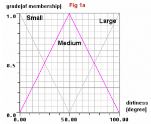
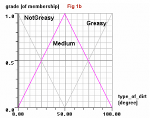
To explain how fuzzy controller works in an automatic washing machine, we use a simplified model where only quantity of dirt and type of dirt are considered as inputs to the controller. An optical sensor is used to measure the transparency of the water, by which the quantity of dirt is then determined. The type of dirt is determined by the different saturation points, as some dirt, such as grease, is less soluble in water and therefore takes longer time to saturate water (water is saturated when the water transparency is almost zero). Each of these two inputs “quantity_of_dirt” and “type_of_dirt” are presented on a scale from 0% to 100%. The decision which the fuzzy controller makes is derived from the rules which are stored in the database as if-then statements as follow:
These rules can be shown as Gaussian membership functions with inputs shown in Fig. 1a and 1b and outputs shown in Fig 2:
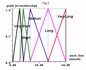
Degrees of membership (DOM) are calculated for each inputs. The sum of Output Component (which equals “Input DOM x Output Set Value” for each component ) is the value for our Crisp Output “wash_time”. A signal is then sent so that the correct washing time will be implemented.
The process for an automatic washing machine is a batch process. A feedback control strategy is used, as the controller takes into consideration the degree of cleanliness (our controlled variable) that we desire in order to make the decision and take action on the manipulated variables. Even though a simple model is used in our case to demonstrate the determination of washing time, we know that this model could be expanded to other manipulated variables such as quantity of detergent, water level, washing temperature, and spinning speed by adding other sensors. For example, by using neuro fuzzy control, fabric type of clothing can be detected by the sensor and the correct spinning speed can be determined to avoid extra creasing of the clothing. The fuzzy controller has also been introduced to the drier to avoid overheating of the clothing by inadvertent human error.
In future, a reiterated process may be used to improve the performance of fuzzy control. The optical sensor could be used to measure the cleanliness of the clothing after the first wash. In this way, should disturbances such as too little detergent added occur and the washing result be less than satisfactory, another wash with corrected action would be implemented using the same process.
Agarwal, M. (n.d.). Retrieved from Tripod: http://softcomputing.tripod.com/sample_termpaper.pdf
Cole, G. (1995, 12 1). Fuzzy Logic, Fabulous Performance. Accountancy.
Fuzzy Control of Washing Machines. (n.d.). Retrieved April 1, 2016, from Concernergy: http://www.concernergy.com/index.php/residential_appliances_fuzzy-control-of-washing-machines_197#more
Fuzzy Logic. (n.d.). Retrieved April 1, 2016, from http://mathematica.ludibunda.ch/fuzzy-logic6.html
Neha Virkhare, R. J. (2014, 1). Neuro-Fuzzy Controller Based Washing Machine. International Journal of Engineering Science Invention, 48-51.
Are you sick and tired of watered down iced-coffee? Do you wish that your iced coffee didn’t become diluted over time? What we propose is both a solution to this problem as well as a novel use of common appliances. Even if you don’t

drink iced coffee, our design concept can shift your view of processes that you may take for granted. While this system can operate at both personal and industrial scales, we envision this system as being most economically relevant on an industrial scale. With the commercialization of coffee ice cubes, private coffee shops and commercial coffeehouse chains will be able to provide their customers with higher quality iced coffee. Our system revolves around the design and control of a process that will brew, store, and freeze coffee. The end result will be frozen coffee that can be dispensed like standard ice cubes.
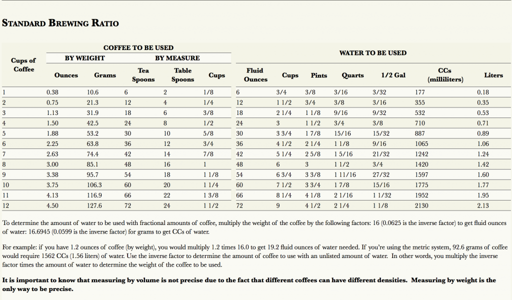
The process begins with the brewing of coffee. More specifically, we will be using a french press system. First, 12.78L of tap or distilled water will be added to the 20L brew vessel. The vessel will then heat the water to 96℃ (with an allowable deviation of -5°C) (1). After this temperature is reached, 0.7656 kg of medium ground coffee beans will be added to the tank. The tank will be stirred vigorously for 10 seconds, then brewed for 4 minutes. After 4 minutes, a european style plunger will gently push the grounds to the bottom of the tank.

The coffee will drain into an air pot style reservoir, then the bottom of the tank will open and dump the used grounds. This brewing process will repeat once the used grounds are dumped and the bottom of the tank is resealed (2). The air pot reservoir will be held at a temperature around 4℃. As fresh, hot coffee is added to the reservoir, the refrigeration will intensify to bring the contents to an equilibrium temperature of 4℃.
The next part of the system will be modeled after an automatic commercial ice cube machine. The coffee from the reservoir will be pumped out and allowed to flow continuously over an ice tray that is cooled via heat-exchanging pipes. These pipes cool the tray by allowing a compressor to cycle refrigerant fluid
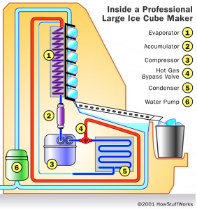
through a condenser, then an evaporator. The constant condensation and expansion of the refrigerant draw heat away from the tray, allowing it to freeze the coffee (3). Once the cubes are formed, which takes approximately 15-40 minutes, a hot gas valve will open and cause the refrigerant to bypass the condensing stage. This results in an increase in temperature of the heat-exchanging pipes, subsequently causing the cubes to melt slightly and release from the tray (4).
The cubes will fall into the storage bin, which will be maintained at a temperature below -25℃, which is the eutectic temperature of brewed coffee (5). As the bin fills up, the ice will come into contact with a “thermostatic bin control thermal well” which will open and signal the ice machine to shut down until the bin needs to be replenished (6).
To begin organizing the overall process, we have determined which variables need to be controlled within the system:
In this system, temperature is critical to the production, storage and freezing of the coffee. Consequently, there should be a relatively narrow effective temperature range for each step in the process. While heating the water which will be used to brew the coffee, it is important to ensure that the water reaches its minimum brewing temperature, 91℃, but does not exceed its ideal brewing temperature, 96℃. Exceeding this temperature, especially if the water were to reach its boiling point, 100℃, will burn the coffee, ruining the batch.
When it comes to storage, the air pot style reservoir will need to account for increases in temperature that occur due to the addition of freshly brewed coffee as it equilibrates to 4℃, an acceptable storage and preservation temperature. The temperature at which the coffee is frozen and the cubes are stored must be controlled at a set point below -25℃, the freezing point of brewed coffee. Rising above the freezing point will be incredibly detrimental to this process because it will prevent the formation of product — coffee ice cubes.
In order to control the aforementioned variables, an additional set of variables must be manipulated. The temperature at which the coffee brews will be controlled by a heating apparatus surrounding the brewing vessel. This is done to ensure an even distribution of heat. There will be a sensor within the tank to determine when its overall temperature is within the acceptable range.
The temperature of the systems that require cooling will also be monitored by an internal sensor. A continual disturbance within the system is the addition of fresh, hot coffee being added to the refrigerated reservoir. As the temperature increases, the sensor within the cooling reservoir will send a feedback signal to a fail-close valve that will increase the flow of refrigerant to the heat-exchanging pipes. If the aforementioned disturbance is not accounted for quickly enough, there will be a fail-open valve that prevents the coffee from leaving the storage reservoir until the contents reach the 4℃ set point. Similarly, as operators retrieve coffee ice cubes from the storage unit, the temperature of the unit will increase. This periodic temperature change will be regulated in a similar fashion to the air pot style reservoir.
To maximize consumer satisfaction, the concentration of the coffee will also be controlled. In order to control the concentration, a sensor will be located within the air pot style storage reservoir, which will be continuously stirred to maintain an even concentration. This sensor will be connected to the water pipe that feeds into the brew tank. The signal from the sensor will regulate the amount of time that the valve is open in order to adjust the amount of water entering the brew vessel. The ability to manipulate the flow of water allows operators to set their desired strength of coffee while also ensuring the the quality of each ice cube is nearly identical.
While one could control the amount of ground coffee beans entering the system, it is less practical than manipulating the flow of water. The addition of water has a direct effect on the overall volume of the tank. However, the addition of coffee beans has an indirect effect on volume since it is directly dependent on the mass of the bean. Manipulation of flow rate of water ensures that the tank will not overflow, which is highly important on an industrial scale. Lastly, the length of time that the coffee brews in the vessel will be manually set by operators depending on their preferences.
No system is perfect, so we must account for and correct errors that will arise throughout the process. In addition to the disturbances discussed above, another potential perturbation can arise during the brewing stage of this process. Although our system will automatically release coffee grounds each time the brew vessel finishes draining, there is a possibility that solid residue will build up in the bottom and on the sides of the brew vessel. To account for this buildup, there will be a sensor that monitors the volume inside the tank. If the volume starts to increase above the set value of 17L, it will notify the system to shut down, and indicate to the operator that the brew vessel must be cleaned.
The commercialization of coffee ice cubes is an innovation that will revolutionize the coffee consumption industry. Through the combination and modification of commercial scale coffee production and commercial scale ice cube production processes, coffee — a precious life-sustaining elixir — can now be consumed in both liquid and solid states.
~ Sara Mikovic, Owen Robinette, Rachel Tritt
Sources