Leaving lights on at full blast for all hours of the night can be wasteful, especially when there are no people around to benefit from that light. Energy is wasted, and checkbooks run thin when it is time to pay the bills. Our idea is to design a system of motion sensor lights that also have a dimming function based on sensed light. The motivations of examining this process are energy and cost reduction. Both can be saved by using automated lights that turn off when there is a lack of movement or where there is enough ambient light.
The controlled variable of this system would be the level of light given off by the light bulb. This variable is manipulated by the change in energy supplied to the bulb. The operating range would be determined by the level of light detected by the light sensor. The system would operate off of two main ranges of operation. The “good” range of operation would be the range in which there is enough natural light, such as during the daytime or when nearby lights are illuminated enough. In this case, a signal would be sent by the sensor to turn off the bulb. The system would turn on upon reaching the “bad” range of operation, in which not enough natural light is present for proper sight. A signal would be sent by the sensor to the controller, causing the bulb to apply light.
While the dimming and motion activating functions are the cornerstones of the system, they would not be necessary to act in the bare-bones functions of a conventional light. Fortunately, in the event of a malfunction, not all functionality would be lost. Therefore, the product would still function as a light without the necessary adjustment of light level. The light level sensor control is an improvement because it saves energy on lights when the energy applied is not necessary. During daylight, it is more efficient for the light to be off. The motion sensor control is an improvement because it makes living alone more manageable. If a person came home from grocery shopping late at night, the automated light sensors would turn on at his porch and in his house as soon as he is within a certain distance.
The motion sensor is another benefit to the operation of the light function. It is supportive of the user experience due to the convenience of an automatic versus manual control. If there is no error reading in the light sensor, the motion sensor does not respond to motion because there is already enough light present. Motion control creates a safer environment such as in parking lots or along sidewalks among other public places. Furthermore, this product is cost effective, since less power is used up by the light bulb than if the lights were on for the whole day.
The manipulated variable is the energy applied, which can have numerous points of manipulation, such as for a daytime and nighttime setting. Once the surroundings reach a certain level of brightness without movement, the system can shut off completely. For examples, after 5 minutes of inactivity or sufficient lights for 5 minutes. At this point, there would be no electricity applied to the light bulb, but there would still be electricity flowing through the sensor so that it could allow for a quick response through the controller. During a lack of motion, energy would be saved due to the light bulb being off.
Because of the presence of two sensors, potential disturbances in either sensor could affect the output. Light level disturbances may include the headlights of nearby cars or lights from television or computer screens. Motion disturbances, like the small movements of bugs flying around the sensor could also have effects. In addition, the sensor would need to ignore the effects of inclement weather, such as rain or snow.
To mitigate these disturbances, a PI controller should be used. A derivative response would be too erratic for the potentially noisy data received by the sensors. The infrared motion sensor, designed to detect high levels of infrared radiation, could be set to only send a signal for detected heat sources of greater than 90°F. Requiring these sources to be localized would avoid issues arising from a summer day when it is above 90°F outside.

Figure 1: Infrared Motion Sensor
The variables of light level and motion disturbances would both be controlled by the manipulation of energy. A sudden detection of motion would require a quick response of energy from the controller while a sudden change in light would require a slow or delayed response. As a person approaches a motion sensor controlled light in a parking garage, it is important that the light illuminate. A slow response in this case would not do much for safety. On the other hand, light disturbances from passing headlights do not need to be addressed by this light system. Changes in light level typically happen over a long time, so a slow response would be acceptable.
The process would be controlled via a third order feedback loop while the motion sensor would contribute a simple unit step to the controller. The following block diagram represents the light and motion sensor system. Xdl and Xdm represent the light and motion disturbances respectively. Gdl and Gdm represent the transfer function of the light and motion disturbances. Xspl and Xspm represent the set points for light and motion. With this block diagram, the system would be developed and the product would be possible. No more useless energy consumption!
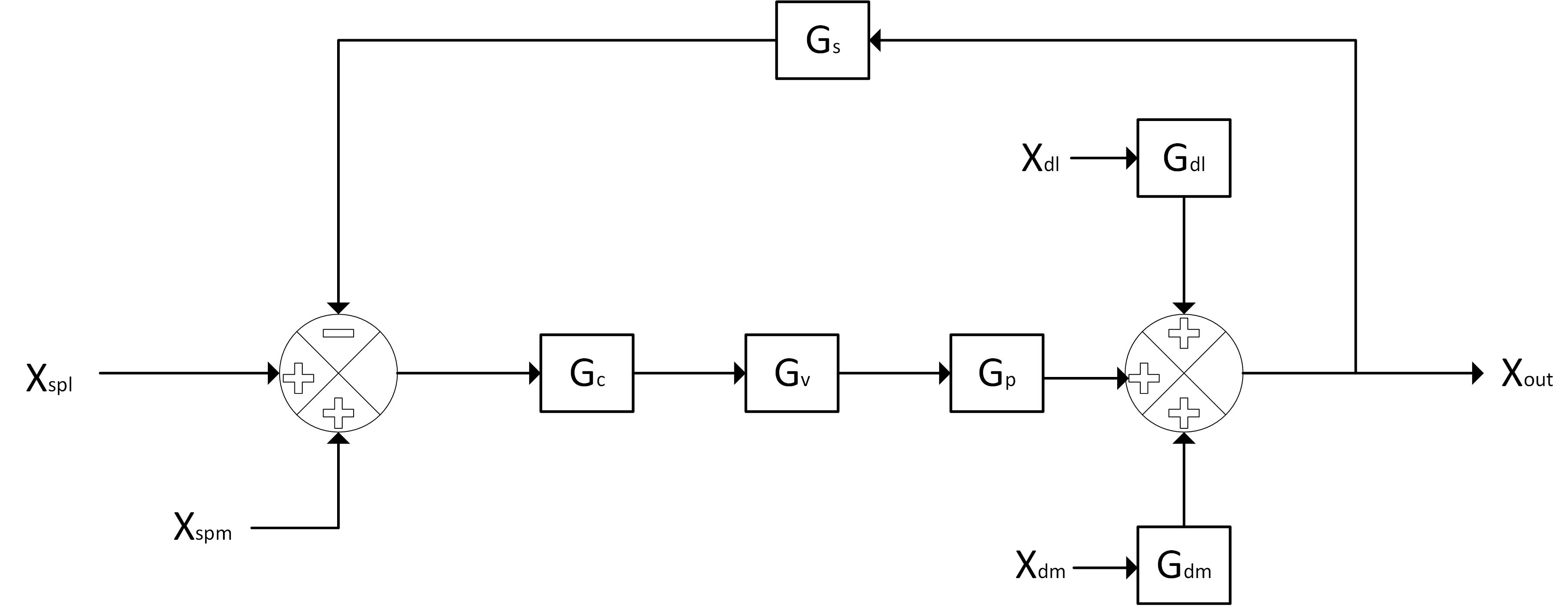
Figure 2: Block Diagram
Reference:
- http://www.safewise.com/resources/motion-sensor-guide