Chocolate Milk Control AM SH VD

An overwhelming problem with the United States population, specifically children, is health and obesity.  A key nutrient in the growth and development of children is calcium.  Many children, however, do not like plain milk, so parents are forced to resort to feeding their children processed, sugary chocolate milk.  Some parents are able to bypass this processed sugary drink, and make chocolate milk on their own simply with milk and a healthier, low sugar chocolate syrup.  The issue with homemade chocolate milk is that there is always too much chocolate syrup, and the syrup sinks, or there is too little and it is not “chocolaty” enough.  In order to help create an evenly mixed drink, self-stirring chocolate milk mugs have been created, but they do not prevent errors in the amount of chocolate syrup added.  By creating a chocolate milk mug that senses the concentration of chocolate in the milk, and reacts accordingly to optimize the chocolate concentration, healthier and more delicious chocolate milk can be made.

The control of the concentration of chocolate milk can be justified due to the increased health benefits from healthier and less processed chocolate syrup.  Additionally, by controlling the concentration of chocolate, it prevents the overuse of chocolate syrup, therefore reducing the cost to the consumer.

As the amount of chocolate syrup added by hand never seems to come out right, the homemade production of chocolate milk must be optimized. It also needs to be optimized because chocolate syrup costs an average of three dollars for 24 oz.  If chocolate syrup is not measured when it is added to the milk, too much could be detrimental to your pocket.  Those couple of cents adds up for the extra syrup that you do not need.  Optimizing the amount of chocolate that is put into the milk will save money by reducing the amount of premade chocolate milk purchased and also by not wasting unnecessary syrup.  Another reason why consumers benefit from optimizing the amount of syrup inside the milk is because making your own chocolate milk can be healthier than drinking the processed, pre-mixed brands.

The first step in starting the process of making the best chocolate milk is to identify the variables that are being affected.  The control variable for this system will be the concentration via the density of the milk, which will be monitored using a sensor.  This sensor measures the density throughout the mixing process, but we are mostly concerned with what the concentration is after the mixing has completed.  Since the sensor measures the density of the chocolate milk, it is important to determine what the optimal measurement is.  This was determined by creating different concentrations within a certain amount of milk.  After a taste test of each, it was determined that the optimal density of chocolate milk is 0.219 g/mL.  Because there is bound to be some slight error, the acceptable parameters for the density of homemade chocolate milk is within 10%, or 0.196 g/mL to 0.239 g/mL.  Although the control of the concentration of chocolate milk is not critical to the function of the mug, it is quite beneficial to the consumer and our purpose is to always please the customer.  The manipulated variable is the amount of chocolate syrup in the milk.  This is the manipulated variable because it can be controlled in order to make the best chocolate milk.  This is the most practical variable to manipulate because it is what makes the milk taste delicious.

The variables that could potentially disturb the way our system works could include the amount of milk that is placed into the mug, the brand of chocolate syrup, and the type of milk.  Different gradients of milk have different densities so the optimal density would need to be adjusted.  The chocolate syrup, too, can differ depending on the brand as each brand of chocolate syrup has a slightly different concentration and density of chocolate taste. While the Skinny Moo Mug is extremely reliable, it can under perform at times.  Although the chocolate milk could suffer minor quality deficiencies due to disturbance variables, the consumer can be at ease because these disturbance variables should be accounted for in the density readings taken by the concentration sensor.  It is recommended that if errors in the chocolate milk taste occur, a spoon be used to ensure complete mixing.  In order to tell if any of these disturbances have affected the delectable, scrumptious taste of chocolate milk, a feedback loop would be appropriate.  A feedback loop is best because the system is reactive.  In other words, the system does not change the amount, or density, of chocolate milk until an error arises.  Additionally, a feedback loop provides an explicit response where the density of the chocolate milk can be changed to a predetermined explicit value.

In order to create the optimal chocolate milk, we will be constructing a variation of the “Skinny Moo Mug.”  As seen in the YouTube video below, built into the mug is a spinner to ensure equal mixing of the chocolate syrup.

https://www.youtube.com/watch?v=xlX4Tyq-ShY

Instead of the standard cap seen in the stock photo, we will be using a patented cap that has an automatic opening and closing flow hole at the bottom.  Instead of leaving the whole cap as an open space, we will create a wall on the ledge labeled 14E in the photo below.  Creating a wall will ensure that one does not drink solely chocolate syrup when they take a sip of refreshing chocolate milk.  Additionally, a hole will be made on the surface labeled 12D in order to allow for one to actually drink out of the mug.  The original opening shown in the picture as G, will be used as the opening to the reservoir to add the chocolate syrup.  In order to automatically open and close the flow hole labeled 14A, the cap needs to be connected to a concentration sensor.

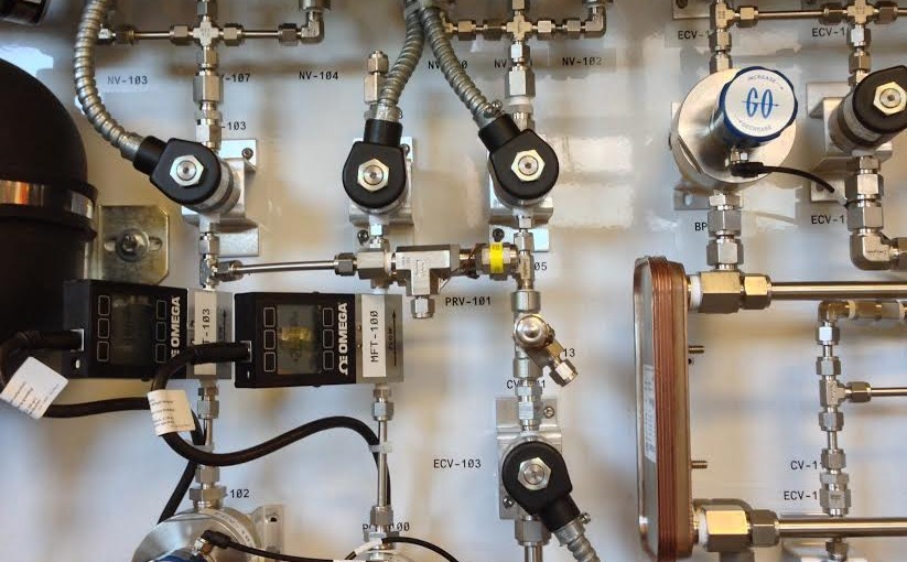
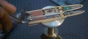
As the cap already comes with the potential to be connected to a sensor, the only task is to insert our own sensor.  The sensor that will be used is called the Microelectromechanical Systems (MEMS) Liquid Density Sensor from Integrated Sensing Systems (as seen on page 5 of http://metersolution.com/wp-content/uploads/2014/08/Micro-liquid-density-sensor-User-Manual-1-1-1-1.pdf).  As seen in the photo, the sensor is smaller than a dime, and will be mounted on the side of the wall of the mug.  As the liquid is mixed and flows throughout the mug, the chocolate milk flows through the sensor.  The sensor will read the density, and therefore concentration of the concentration of the chocolate milk.  The MEMS sensor will be pre-programmed to transmit the density data to the receiver that is already in the cap.  The receiver will also be pre-programmed to either open or close the flow hole depending on the density sent to the receiver.  The mug with the patented cap and density sensor will make for the most delicious, optimal chocolate milk.


References:

http://metersolution.com/wp-content/uploads/2014/08/Micro-liquid-density-sensor-User-Manual-1-1-1-1.pdf

http://www.google.com/patents/US8678220

https://www.youtube.com/watch?v=xlX4Tyq-ShY

US08678220-20140325-D00000.png


Need for (Controlled) Speed

Cameron Darkes-Burkey and Tyler Monko

Not many things are more relaxing than setting the cruise control to 70 miles per hour on a long, empty stretch of highway and letting your mind wander as you let your car carry you to your destination.  As the miles go by, you are able to reminisce about all of your favorite events in your past.  As you are thinking about your first time that your parents took you to an amusement park, you are able to vividly remember everything about your favorite roller-coaster to the point where you think you can feel the sudden stop that the coaster makes halfway through the ride.  Almost too vividly as you are snapped out of your thoughts by your car unexpectedly rear-ending another vehicle on the now not so empty stretch of highway.  Now, imagine the same scenario except instead of your car colliding with the vehicle that seemingly appeared out of nowhere, your car slows its speed and follows behind the other vehicle at a safe distance.  Although this technology, which commonly is referred to as Autonomous Intelligent Cruise Control, may seem like a feature from the future, it actually is currently used in many of the vehicles of today.

Autonomous Intelligent Cruse Control (AICC), unlike the traditional cruise control that just keeps your speed constant, aims to maintain a constant speed as well as a safe driving distance with the other cars on the road.  To function as intended, AICC must be able to control both the speed of its respective vehicle and the distance between its vehicle and the vehicle that it is following.  These are our controlled variables or what we are trying to maintain at a certain set point. Because of outside factors, it is impossible for even the best technology to prevent the speed from fluctuating.  Since large fluctuations not only affect the safety of a vehicle’s passengers but also may result in traffic citations such as speeding tickets, there needs to be a maximum range in which the speed can vary from the desired set point speed.  Since police generally do not issue tickets for speeds that exceed the posted speed limit by less than 5 miles per hour, the acceptable range allowed by the AICC should be within three miles per hour of the desired speed.  Keeping the range within 3 miles per hour leaves some additional room for error.  A “good” range for the distance of cars is based on the standard rule of thumb to stay 6 seconds behind the car in front of you (this is often the rule for poor weather, so will add a factor of safety during good weather conditions to stay on the safe side). Therefore, using some basic math, we will keep our distance (in feet) more than ((8.8ft*hr/miles)*v) where v is the velocity of your car in mph. Our range for this is a little more strict, allowing for less fluctuation. We believe that the error for the following distance should deviate by no more than 5% from the safe distance set point.

The control of both the speed and following distance is critical to the function of AICC. The distance is especially important as it will help to prevent accidents, and without the maintaining of speed, the primary function of cruise control will be lost. This process is an improvement to driving because it is safer and more economical. By using AICC, the car will be more fuel efficient as the driver will not be constantly alternating pressing the gas and brake pedal down as most drivers do. Also, the safety of the driver will be improved because AICC will help keep your car a safe driving distance away from other cars and reduce rear-end collisions.

Since the speed of the vehicle and the following distance cannot be directly controlled (i.e. they are directly affected by other processes in the car), they will have to be altered in another way.  By manipulating variables that can be directly changed by a controller, such as the pressure of the breaks on the wheels and the position of the throttle, the speed and following distance can be maintained within their respective ranges. Additional pressure of the breaks on the wheels can slow the car down or bring it to a stop, and, by opening up the position of the throttle, the car will speed up. Both of these aspects of the process can be controlled, and in this case, it makes very practical sense to do so.

Excluding exceptional circumstances such as Edward Cullen stopping your car with a stiff arm, there are various disturbances during normal driving conditions that will affect the speed and following distance.  Disturbance variables are unexpected or unplanned changes that affect the controlled variable. For example, terrain changes including elevation variations and road types will affect the speed of the car. Weather changes could also have a presentable effect.  To account for these speed changes, either pressure needs to be applied to the brakes or the position of the throttle needs to be changed. For distance monitoring, changes in the speed of the preceding cars would also require sudden alterations to the manipulated variables.

For our process, a feedback loop is the best since it responds to any disturbances to our controlled variable and will enact changes on the manipulated variables accordingly. A feedback loop will take into effect any disturbance variables that ultimately affect the controlled variables because it takes its measurement after they have already had their full effect on controlled variables causing deviations from their set points.

block diagram

“Driver behavior in vehicle following has been an active area of research since the early 50’s. In vehicle following, the human driver acts as a controller. He senses velocities, distances, and accelerations and decides about control actions accordingly. In order to study these human control actions and their interaction with the vehicle dynamics, several investigators consider the development of mathematical models that mimic human driver behavior” (Ioannou and Chien 658). One commonly studied model is shown in Fig. 1. In this block diagram, note the Reaction Time Delay and the need for Central Information Processing and Neuro Motor Dynamics all of which slow the reaction time down and increase the possibility of an accident. With automation and good sensors involved with Autonomous Intelligent Cruse Control, this human reaction time is eliminated. This allows for safer inter-vehicle interactions giving you the opportunity to occasionally reminisce about those vivid memories.

Citations

Petros A. Ioannou and C.C. Chien. “Autonomous Intelligent Cruise Control.” In IEEE Transactions on Vehicular Technology, Vol. 42, No. 4, November 1993. Web. Site visited on 16 Mar. 2016. <http://ieeexplore.ieee.org/stamp/stamp.jsp?tp=&arnumber=260745>.

Engineering Explained. “How Adaptive Cruise Control Works – Step One for Autonomous Cars.” YouTube. YouTube, 11 Nov. 2015. Web. 16 Mar. 2016. <https://www.youtube.com/watch?v=IMYi3G7dkU4>.

Self Regulating Treadmills RM, GL, NW

Most people find running on treadmills to be incredibly boring. However, self-regulating treadmills can take the monotony out of typical indoor exercise. Treadmill technology has increased in the last decade to include features such as heart rate sensors, calorie counters, and even TVs. However, the runner has always been constrained to running at a constant uniform pace. The runner has to pick their speed and adjust to that. This is not compatible with the natural variation in pace that runners experience outside. Self regulating treadmills have already been researched, prototyped and tested however they have not been commercialized or patented yet. These treadmills are able to detect the speed of the runner on the treadmill in order to control the pace of the running belt below the runner’s feet.  When the runner speed up, the belt’s speed will increase.  The opposite is also true.  When the runner slows down, the belt will decrease its speed.


This additional control is not vital to the function of the treadmill. However, the additive feature gives the runner the freedom to set the pace of his or her own workout instead of being controlled by the treadmill. It is often difficult for a runner to stay at the same pace the entire time he or she is running. This treadmill allows the runner to change speed quickly without having to push buttons or set a new pace on the monitor. Additionally, according to preliminary testing, this additional feature can improve the athletic performance of the runner. When tested on both regular and self regulating treadmill, experienced runners improved their VO2 max scores (a measure of the maximum volume of oxygen an athlete can use) by 4 to 7 percent. Controlling the position of the runner on the treadmill is also important for safety reasons. If the runner were to stumble or misstep, the belt would be able to slow down to allow the runner to safely recover. Also accidents which occur when people run into or fall off the treadmill would be reduced. Some treadmills like the one below have a safety clip to try to stop the treadmill if the runner falls too far behind. However, it doesn’t prevent the runner from running too far forward. A good range of operating conditions for this parameter would keep the runner within a foot from the center of the belt.

treadmill1

The treadmill works by adding a sonar range finder (shown below), a transmitter, a micro-controller and a computer. The sonar finder is placed at the back of the treadmill and is used to measure the distance between the runner and the sonar finder. Typically, the sonar is aimed between the shoulder blades of the runner since the position of a runner’s legs cycles while the position of a runner’s back is relatively consistent. The sonar finder measures the distance between the runner and the sonar device. It then sends this signal through the transmitter to the micro-controller. The process uses a feedback system, which makes changes to the system based on measurements in the output. As a consequence, this forms a reactive system. The micro-controller compares the runners current distance from the back of the treadmill to the distance between the back of the treadmill and the midpoint of the treadmill. If the measured distance is larger than the compared value, the belt speeds up to bring the runner back towards the middle. Conversely, if the measured distance is smaller, the belt slows down to allow the runner a chance to catch back up to the center.

Job # 150150 Steve Devor with Treadmill PAES Physical Activity and Education Services APR-08-2015 Photo by Jo McCulty The Ohio State University

The controlled variable is the distance between the runner and the back of the treadmill. In order to control the distance, the treadmill manipulates the speed of the belt via the mechanical work done by the rotators. The range of the sonar’s distance would be from the end of the treadmill to the front of the treadmill. Other readings should be at saturation because a person has to be on the treadmill. The controller would also limit the maximum possible speed as a safety precaution. If the person’s position changes the controller should not overshoot the maximum safety limit because it might cause the runner to fall. The minimum speed of the treadmill would be zero.

sonar-treadmill

Potential disturbances to the system include dramatic changes in runner velocity. If a runner were to stumble, trip or fall, their speed would be drastically reduced. Also the sonar needs to be able to tell the difference between a runner’s foot and a different object. For example if a runners water bottle fell right in front of the sensor, we wouldn’t want it to slow down too quickly thinking that the runner is too close to the sensor. Sonar sensors are already capable of differentiating between humans and other objects. Sonars send out ultrasonic sound waves that are then reflected off of people and things and returned to the sensor. The time it takes for the waves to return is used to calculate the distance. However, the intensity can be used to determine if the wave is being reflected off of a human. Several factors affect the intensity of the reflection including size and texture. Humans return ultrasound waves within a relatively small range of intensities. Therefore, if an intensity falls within this range it is extremely likely to be from a human.

The sensor would use a feedback loop. It would be hard to determine variances in the runners input. It is a lot easier to determine differences in a runner’s speed. If a runner wanted to increase his or her speed, he or she would run harder. Therefore, the runner to move forward on the treadmill. This would cause the sensor to detect the changing distance from the runner to the sensor. The sensor would transmit a signal and it would be compared with the set point signal. The controller would then speed up the treadmill until the runner is back at the set point distance.

In order to mimic the natural fluidity of running outdoors, treadmills could soon become capable of matching the runner’s pace instead of operating at a constant speed. This additional feature would improve athletic performance of the runner while hopefully creating a more exciting workout.

Works Cited

Bonar, Tom. “MaxBotix Inc., High Performance Ultrasonic Rangefinders.” Kiosk Sensor and People Detection. N.p., 07 Oct. 2012. Web. 31 Mar. 2016.

Grabmeir, Jeff. “​New Design Makes Treadmill More like Running Outdoors.” News Room. N.p., 14 Apr. 2015. Web. 31 Mar. 2016.

Vergara, William C. “Science Explorations: Journey Into Space: Radar and Sonar | Scholastic.com.” Science Explorations: Journey Into Space: Radar and Sonar | Scholastic.com. N.p., n.d. Web. 31 Mar. 2016.

Bullseye!

In the pursuit of power, mankind has often followed the path of war after diplomacy yielded no results. In this regard, countries have always looked for ways to tip the scales of power in their favor: from the invention of the first trebuchet to the use of the atomic bomb, the technological advancements made in warfare have been mind-blowing. Even though some of these advancements have often led to the bettering of societal technologies, there have always been tragic costs associated with wars – the loss of innocent life. In recent wars, there has been a climb in these types of deaths. To battle the loss of life associated with stray bullets or inaccurate shootings, technological advances have been researched to mitigate this growing trend.

smart_bullet

DARPA, the Defense Advanced Research Projects Agency, has recently unveiled a new type of bullet that would decrease the inaccuracy of bullets fired. The process of controlling this aspect would mitigate both the loss of innocent life as well as target the not-so-innocent groups during times of war. Dubbed the EXACTO bullet (extreme accuracy tasked ordinance bullet), it would be capable of adjusting its flightpath to the specifications described by the shooter. The controlling variable in this scenario would be the flight path of the bullet. If the flight path of a bullet could be pre-determined, it would both increase the chances of success in a mission as well as decrease the chances of civilian casualties. A good operating range would then be the bullet finding its appropriate mark; a bad operating range would be hitting anything besides its appropriate mark. Since the saving of innocent life is always paramount in any given situation, the control of this specific variable would be very critical to the operation.  

To control this application, several factors would have to be taken into account. To test the potential of controlling the accuracy of a bullet, DARPA has looked into incorporating controlling mechanisms into 50 caliber bullets. These large caliber bullets are typically associated with long range sniper rifles that rely on large amounts of precision and accuracy due to the long distance that usually exists between the shooter and target (up to 1500m). Although bullets are fired from these rifles at roughly 800m/s, several factors come into play at such extreme lengths that can alter its path. Some possible factors include wind speed, humidity, temperature, elevation above sea-level, air resistance, muzzle velocity, and gravity. Since it is impossible to control disturbance factors, such as wind speed or temperature, the technology within and on the bullet would work to counteract these factors, or would be constantly fed through some controlled process to account for these variables. A control system that could compensate for these factors would minimize the human error that arises from shooting at long distances.

Moving targets pose the largest challenge for shooters. In most scenarios, snipers will wait until the target is stationary before taking their shot. If that controlled variable cannot be achieved, a new decision comes into play: the anticipation of where the target will be at a given time in the future. Regular bullets do not change their trajectory once released from the barrel, so if the target moves, the bullet could miss the target and hit someone else who wandered unwittingly into its path. At such great distances, the chance of this happening is higher than for close-up shots, so snipers must take enough time to set up before taking a long-distance shot. Once the shot is taken, the shooter’s position becomes compromised, and the opportunity to hit the target has passed. “Locking” onto the target and having the bullet change trajectory in response to the target’s motion, or even incorrect aim, could significantly increase the number of bullets that reach their targets. DARPA’s team has been able to correct for this by controlling the bullet to change trajectory in response to the moving target.

images

The bullet uses a feedforward response system, meaning it will detect the change in location of its target while both are in motion, and it will alter its direction in order to re-focus on its target. DARPA has not unveiled its full secrets surrounding the technology of the bullet; however, the basic mechanism for the path change is known. It does so by following a laser-designated mark, altering its flight path by moving small fins up to 30 times a second, to adjust for changes in position. With this new technology, targets should be hit more often, allowing soldiers to fight more effectively than ever. Similar technology has proven efficient in smart bombs; however, the challenge here was developing electronics that would be small and capable enough to fit inside the base of the bullet. Additionally, not only would the bullets be more accurate, but they would also allow for shots to be taken more quickly. The bullet will be able to account for inaccuracies in aim, which will allow the sniper to be slightly less accurate and much faster at taking a shot. Their ability to move in and out of position quickly will reduce the risk they pose to themselves and their unit by compromising their position.   

Screen Shot 2016-03-30 at 12.05.30 PM

This YouTube video demonstrates and explains the target-locking  technology:

https://www.youtube.com/watch?v=PjdEweHYxEk

Some sample moving-targets are shown in this YouTube video:

https://www.youtube.com/watch?v=YoOaJclkSZg

Large leaps in bullet technology have already been made. Over the course of centuries, bullets have progressed from round, spherical shapes, to the elongated egg forms with a pointed end, which are used today. This step significantly cut down on the air resistance the bullet encounters, leading to the increase in the total travel distance of the bullet through the air (from 100 yards when using Civil War muskets to roughly 7,000 yards for the sniper rifles used today). With small changes having such significant effects, all factors should be considered when attempting to make an improvement towards a certain goal. To improve accuracy, the factors that need to be controlled the most are wind speed and the location of the target. Large gusts of wind can derail a bullet from its flight path, and the flight path of an ordinary bullet does not change based on movement of the target. Because of the tiny fins located on the shell of the bullet, obstacles, such as these, could be overcome with a slight adjustment relayed from the laser-marked target to a guidance system located in the bullet. Since controlling these outside factors is impossible, the next step forward would be to counteract these effects by inserting a feedforward loop. A feedforward loop works by monitoring disturbances in the path of the bullet before it reaches its intended target. The control system will monitor the wind speed and location of the person, and if either of these change, the controller will alter the path of the bullet before it hits the person. If the system works properly, the target will be hit every time.

images-1

Moving forward, many challenges arise that make the design of this system difficult, and limitations require alternative ideas. Since the bullet would still be travelling at such high velocities, any type of system correction would have to be done in less than three seconds (taking into account the distance to the target is roughly 2400 meters away). Because of this limited window of correction, a fail-safe should most likely be installed, which would cause the bullet to self-destruct or stop mid-flight.

With improved technology, the country will grow stronger. War will be completed more efficiently, and more soldiers will return home quickly and safely. Fewer civilians will be lost in the process. These bullets could provide the technological advantage needed to come to a quick resolution regarding political conflicts while minimizing the interaction of those not directly involved.  

Hard Water is More Hardcore, Then You Might Think

rusty-water-pipes-dreamstime_l_29875576
“Water Filters – Temecula Valley.” Green Cow Energy Consultants. Green Cow Energy Consultants, n.d. Web. 28 Mar. 2016. <http://www.greencow-energy.com/water-filtration/>.

Water softening is a technique that serves to remove the ions that cause  water to be hard, in most cases calcium and magnesium ions. Iron ions may also be removed during softening. The best way to soften water is to use a water softener unit and connect it directly to the water supply. A water softener moves hard water containing calcium and magnesium ions into the mineral tank.

Klenck, Thomas. "How It Works: Water Softener." Popular Mechanics. Popular Mechanics, 01 Aug. 1998. Web. 13 Mar. 2016. .
Klenck, Thomas. “How It Works: Water Softener.” Popular Mechanics. Popular Mechanics, 01 Aug. 1998. Web. 13 Mar. 2016. <http://www.popularmechanics.com/home/interior-projects/how-to/a150/1275126/>.

The ions exchange with the sodium ions inside the sodium-rich beads in the mineral tank. The sodium ions go into the water, and the beads become saturated with calcium and magnesium, which enters the unit into a 3-phase regenerating cycle. The backwash phase reverses water flow to flush dirt out of the tank. Next, the recharge phase carries the concentrated sodium-rich salt solution from the brine tank through the mineral tank.Sodium collects on the beads, replacing the calcium and magnesium, which go down the drain. Finally, excess brine flushes from the mineral tank and the brine tank refills.

Soft water is important to us because:

  1. Hard water causes boiler and cooling tower breakdowns.
  2. Water softeners improve working, and create a longer lifespan of solar heating systems, air conditioning units and other water-based applications.
  3. Hard water clogs pipes by a higher risk of lime scale deposits. Therefore, hot boilers and tank efficiencies are reduced, increasing the cost of domestic water heating by 15-20%.
  4. Water softening means expanding the lifespan of household machines, like washers.

Water softeners need control.

How????

Hard water is not a health risk; however softening water adds substantial lifespan to pipes and other water-based machines, which saves money! We seek to control the concentration of magnesium and calcium in the ‘soft’ water output. This range is determined by the Water Quality Association. Thomas Klenck of Popular Mechanics Magazine writes that “Water hardness is measured in grains per gallon (GPG) or milligrams per liter (mg/l, equivalent to parts per million, or ppm). Water up to 1 GPG (or 17.1 mg/l) is considered soft, and water from 60 to 120 GPG is considered moderately hard. A water softener’s effectiveness depends on how hard the incoming water is. Water over 100 GPG may not be completely softened”. The success of a water softener is determined by the decrease in water hardness or the ability to obtain water under the “soft” limit.

There are multiple options for manipulated variables. One option is to control the flow of salt resin between in the brine tank and mineral tank. Studies established that “each cubic foot of resin can effectively remove calcium and magnesium from about 3,200 gallons of hard water, which the Water Quality Association defines as 10 grains per gallon hardness. The process adds about 750 milligrams of sodium to each gallon of water, which the U.S. Food and Drug Administration considers to be in the “low sodium” range for commercially sold beverages” (Wight). It makes sense to control this variable because it affects the quantity of water you can process in a given amount of time based on the hardness of the incoming water. A second manipulated variable would be overall size of the water softener. The larger the tank the more water processed in a time interval and the more surface area necessary in the salt resin for effective conversion of hard water to soft water.

The control in a water softener is found in its recharge methodology. There are three varieties of recharge method found in practice.

water_softener_diagram
“Water Softeners —.” MRWPCA : Go Green : Water Softener Alternatives. Monterey Regional Water Pollution Control Agency, n.d. Web. 18 Mar. 2016. <http://www.mrwpca.org/green_water_softeners.php>.

Three Types of Control

  • Automatic Regenerating System (during recharging, soft water unavailable)
      1. Electric timer flushes and recharges the system on a regular schedule
      2. Time clock set by user
      3. Disadvantages: Generally cost more over time due to regularly scheduled recharge causes no
        conservation of salt and water
  • Computer Monitoring (reserve resin capacity, some soft water available)
      1. Computer watches how much water is used.
      2. When enough water passes through the mineral tank to deplete the beads of sodium, computer triggers regeneration.
  • Mechanical Water Meter
    1. Water meter measures water usage and initiates recharging.
    2. Mineral tank only recharged when necessary; conserving water, salt and cost.
    3. Single Resin Tank
      1. Separate salt tank with fixed capacity to remove ions from water
      2. Go through a regeneration process each time resin limit is reached
      3. Disadvantages: Soft water unavailable during recharge
    4. Double Resin Tank
      1. Separate salt tank monitored by microprocessor meter or electro-mechanical meter
      2. Advantages: One tank always available for softening, while other recharges; continuous supply of soft water uninterrupted
      3. Disadvantages: Costs more
    5. Microprocessor Meter
      1. Turbine spins as water is consumed and an electronic sensor communicates the rate of spinning to the computer control system.
      2. Information allows computer to decide when regeneration should be initiated based on water hardness level, which is set by user.
      1. Electro-Mechanical Meter
        1. Similar turbine to microprocessor meter, but connected to meter by a cable.
        2. Once capacity has been reached, electrical motor initiates regeneration.

DISTURBANCES????

During normal use, there will be natural variance in the incoming water hardnesses which requires that your controller be able to change the time spent in the tank and amount of salt resin present to soften the water to within required limits. A water softener could also run out of salt resin within the brine tank demanding refillment by user and thus causing a period without “soft” water.

To account for the natural variance in the incoming water hardness, a feedforward loop could be implemented. A feedforward loop occurs when action and decision tasks are based on the input concentration stream. The incoming water hardness would be measured, sending a signal to the salt resin in the brine tank. Based on whether the incoming water was more or less hard, then a decision to increase or decrease the salt resin flow from the brine tank to the mineral tank would occur as the action.This type of feed forward loop is not used in practice. Another way to account for natural variance in the incoming water hardness would be to implement a feedback loop. A feedback loop occurs when action and decision tasks are based on the output concentration. The outcoming water hardness would be measured and a signal would be sent to the brine tank. The brine tank would make a decision based on the hardness of the outcoming water. The action would occur by increasing or decreasing the amount of salt flowing from the brine tank to the mineral tank coinciding with water that is too hard and water that is too soft.

Now please enjoy this really corny video about how a water softener works:


Current Bibliography:

“Water Softener Use Raises Questions for Septic System Owners.” Center for Watershed Science and Education. University of Wisconsin – Stevens Point, 2011. Web. 13 Mar. 2016. <http://www.uwsp.edu/cnr-ap/watershed/Pages/GWSofteners.aspx>.

Wight, Chuck, PhD. “How Do Water Softeners Work?” Scientific American. Scientific American, 24 Sept. 2001. Web. 13 Mar. 2016. <http://www.scientificamerican.com/article/how-do-water-softeners-wo/>.

Klenck, Thomas. “How It Works: Water Softener.” Popular Mechanics. Popular Mechanics, 01 Aug. 1998. Web. 13 Mar. 2016. <http://www.popularmechanics.com/home/interior-projects/how-to/a150/1275126/>.

“Water Softener Frequently Asked Questions.” Lenntech, 2016. Web. 13 Mar. 2016. <http://www.lenntech.com/processes/softening/faq/water-softener-faq.htm>

Kegerator

CHE 324 Process Controls Project – Kegerator

Kegs have played an integral role in the storage, transportation and dispensing of beverages for many years. Historically, kegs were constructed using wood but nowadays they are typically made of stainless steel.  A keg, or half-barrel is a 15.5 U.S. gallon vessel. A quarter-barrel has a volume of 7.75 U.S. gallons. Generally a keg is a vessel smaller than a barrel; thus, it is 30 gallons or smaller. A manual pump is used to generate pressure, pushing the beverage out of a hose.  Keeping the liquids somewhat insulated, and allowing easy access; a keg is a great way to serve beverages at social gatherings.

Keg

Figure 1 – Inner view of a Keg

Unfortunately, kegs do have a few shortcomings.  While they do provide some degree of insulation, they cannot cool the beverage or control the temperature.  A traditional keg also requires manual pumping, which can be tiresome and waste time.  These issues can be solved with a Kegerator, a specialized refrigerator built to work with kegs.  Kegerators are generally designed for use with kegs, but they are gaining popularity for dispensing other types of drinks, most notably wine, cold brewed coffee, kombucha, and soda. With home brew kegs, you can put whatever liquid you want inside the keg, pressurize it and dispense it with a kegerator. Different types of liquids require different alterations to the dispense system. Wine and cold brewed coffee use a CO2/Nitrogen blend to pressurize the kegs. These types of drinks also require all stainless steel contact with the dispense system fittings because the higher acid content can corrode the chrome plated brass normally found in dispense systems.A kegerator has a built in control system to regulate temperature, working just like a typical refrigerator.  To add pressure, a compressed gas tank is attached instead of manual pumping.  A gas mixture, high in CO2, is sent through a regulator to keep the contents of the keg at constant pressure, so the beverage will be dispensed when a valve is opened.    

A kegerator solves many of the issues associated with a typical keg, but we believe the system could be improved further.  With a kegerator, careful care must be taken to maintain proper levels of dissolved carbon dioxide.  Typically, a user first chooses a temperature as a set point for the system.  At that given temperature, the regulator pressure must be set to a specific value to ensure the right amount of carbonation in the beverage.  This is not the most direct way of controlling CO2 levels, and also means that the user cannot adjust pressure levels as they like to alter the flow rate of the beverage out of the keg.  Because of this, at low pressure settings the beverage is pumped out too slowly for a social gathering with many people and at high pressure settings the turbulent flow out of the hose causes too much foam. 

kegerator

Figure 2 – Kegerator

We believe that with a few modifications to the design, and an added control system, we could make improvements to the Kegerator. These improvements would would exponentially enhance the experience of the consumers, as CO2 increases the life of the beverage and temperature further enhances its taste.  Further temperature has a formidable effect on both viscosity and solubility of the liquid.

As the temperature of a solution is increased, the average kinetic energy of the molecules that make up the solution also increases. This increase in kinetic energy allows the solvent molecules to more effectively break apart the solute molecules that are held together by intermolecular attractions. The average kinetic energy of the solute molecules also increases with temperature, and it destabilizes the solid state. The increased vibration (kinetic energy) of the solute molecules causes them to be less able to hold together, and thus they dissolve more readily. The impact of increasing temperature will be to slow down the sphere in gases and to accelerate it in liquids. When you consider a liquid at room temperature, the molecules are tightly bound together by attractive inter-molecular forces (e.g. Van der Waal forces). It is these attractive forces that are responsible for the viscosity since it is difficult for individual molecules to move because they are tightly bound to their neighbors. The increase in temperature causes the kinetic or thermal energy to increase and the molecules become more mobile. The attractive binding energy is reduced and therefore the viscosity is reduced. If you continue to heat the liquid the kinetic energy will exceed the binding energy and molecules will escape from the liquid and it can become a vapor.

Typically, a gas will increase in solubility with an increase in pressure. This effect can be mathematically described using an equation called Henry’s Law. When a gas is dissolved in a liquid, pressure has an important effect on the solubility. William Henry, an English chemist, showed that the solubility of a gas increased with increasing pressure. He discovered the following relationship:

C = k * Pgas

In this equation, C is the concentration of the gas in solution, which is a measure of its solubility, k is a proportionality constant that has been experimentally determined, and Pgas is the partial pressure of the gas above the solution. The proportionality constant needs to be experimentally determined because the increase in solubility will depend on which kind of gas is being dissolved.

The goal of this control system would be to keep temperature and dissolved carbon dioxide levels in the beverage (the controlled variables) as close as possible to a desired set point, as well as to give the user the ability to adjust the pressure in the keg as desired.  Operating ranges for temperature and CO2 level are based off of the user’s preferences. Guidelines for these are often provided by the manufacturer of the beverage.  While controlling this system is very critical for it to function, it will add enjoyment to the user’s experience.  

We plan on optimizing the Kegerator by adding a nitrogen tank in addition to the existing carbon dioxide tank.  Both tanks will have a valve (that can be turned to varying degrees of openness) linked to a controller.  After the valve, both tanks will have a regulator (set to the same pressure).  These lines will both feed into the keg.  A sensor to detect dissolved carbon dioxide in the beverage can be placed inside the keg.  The refrigeration unit acts exactly as a typical mini-fridge.  A display on the outside will allow the user to specify a set point for temperature and dissolved CO2 levels. Therefore, this system would employ a feed back loop, wherein the temperature and CO2 levels in the kegerator would be constantly monitored. If these values fall outside the user’s preference, the manipulated variables would be signaled. The major advantage of such a feed back system is that it’s reactive to disturbances in the surroundings, as it automatically compensates for any such differences by manipulating the required variables.

regulator

Figure 3 – CO2 Regulator

For this system, manipulated variables are the electrical power sent to the compressor and the valve positions for the nitrogen and carbon dioxide tanks.  Pressure in the tank could possibly be considered another controlled variable and in this case, the manipulated variable would be the regulator openness, with the user acting as the controller.  

A few disturbance variables exist for this application, too.  Changes in temperature surrounding the system could affect the temperature of the contents of the keg. Changes in outside temperature could also affect the pressure and flow rate of the gas from the tanks. Finally, changes in altitude could affect pressure and the desired carbon dioxide levels in the beverage.

References
“How to Make Cold Brew Iced Coffee.” How to Make Cold Brew Iced Coffee. N.p., n.d. Web. 31 Mar. 2016.
“Solid Solubility and Temperature – Boundless Open Textbook.” Boundless. N.p., n.d. Web. 31 Mar. 2016.
“How Does Temperature Change Viscosity in Liquids and Gases?” How Does Temperature Change Viscosity in Liquids and Gases? N.p., n.d. Web. 31 Mar. 2016.


Solar Divide: Controlling the Sun

“Following the light of the Sun, we left the Old World.”

-Christopher Columbus

Recently, I’ve been approached by a friend of mine who has started a solar energy company called Solar Divide. They focus on the hybridization of existing solar farms through the combination of solar thermal systems with traditional solar panels. I am interested in joining their team, but before I do so I want to make sure that their current product–the Dual Spectrum Solar Harvester–is a sound investment both scientifically and economically.

DSSH

The Dual Spectrum Solar Harvester (DSSH) expands the range over which solar irradiance can be absorbed and converted into electricity. Understanding that photovoltaic cells capture energy from the visible light spectrum, traditional solar panels lose a large portion of the spectrum in the infrared and ultraviolet ranges.

spectral-irradiance

In order capture this lost energy, DSSH replaces the mirrored trough used in traditional concentrated solar power (CSP) systems with a visibly transparent, infrared and ultraviolet reflective trough that could be placed over new or existing photovoltaic solar panels. This allows for the simultaneous collection of photovoltaic and thermal energy.

Understanding all of this, I am left with a few questions and concerns:

  1. How does this integration of these two technologies (CSP and PV) impact the overall efficiency?
  2. What can be done to ensure that this system maximizes its energy conversion to electricity?
  3. What constraints does solar generation face with respect to generation and demand slates?
  4. Lastly, how does storage of energy impact the system and electrical grid as a whole?

Overall, many of these questions can be analyzed through the understandings of process control. So, let’s think about this…

In terms of process control: What Are Our Significant Variables?

Manipulated Variables

Controlled Variable Deviation Variables
 Incident Angle of Paneling

Electricity Output

Insolation

 Energy to Storage/Grid

Cloud coverage

 Flow Rate of Working Fluid through pipe  Electricity Demand

With solar panels, the main variable that we are trying maximize is the output of electricity that goes into the power grid. This too is true for concentrated solar thermal systems, however, intermediate controlled variables are necessary to convert the heat into electricity.

But before we talk about power generation, it’s important to understand the demands of the electrical grid. Throughout the day, everyone uses electricity at different magnitudes which poses a disturbance to the generation of that grid (see Figure below).

elec_load_demand

This large flux in energy demand makes solar generation a true process control issue. To account for this, many solar generation plants use certain types of storage or battery management systems in order to have what is know as “dispatchable” energy. In general, the below schematic demonstrates the general layout of a typical photovoltaic solar farm.

Screen Shot 2016-03-18 at 2.17.51 PM

However, the product that Solar Divide is attempting to create combines the typical solar farm with the parabolic trough. Even though the issue of electricity demand slate still remains, let’s look into the variables that affect the power generation of CSP.

Since the main source of power–solar radiation–cannot be controlled, the only simple controllable variable on the DSSH then becomes the flow of fluid within the solar receiver. This fluid flow can then be optimized so as to help increase the efficiency of thermal storage and power generation.

Figure3-1_0

The main purpose of a control system on the DSSH would then be to maintain the outlet oil temperature at a desired set point in spite of disturbances from the environment. Since many variables such as (1) the solar irradiance level, (2) the mirror reflectivity, and (3) the inlet oil temperature all can impact the outlet temperature, it is difficult to maintain a desired output with a fixed parameter controller. Since a controller’s response rate and dead time have high oscillations and variation, they must be detuned with low gain and therefore retain sluggish responses in order to compensate for the various environmental factors.

So, you may be wondering…where does one even start to be able to model a system like this?

It’s simple. We start with a balance of energy. (The following equations may be attributed to Camacho et al. and the full citation may be found at the end of this post.)

One must first dilineate all of the heat flows in and out of the system. This may be understood to be in the equation below:

Screen Shot 2016-03-26 at 6.03.11 PM

  • T is the outlet temperature of the field
  • Tin is the inlet tem- perature.
  • C is the heat capacity of the field
  • I is the solar radiation
  • Sfi the total reflective surface of the field
  • Kopt is the optical efficiency of the mirrors
  • no is a parameter taking into account the cosine of the incidence angle between the sun vector and the solar field
  • q is the oil flow
  • ρf and Cf stand for the density and the specific heat of the fluid respectively
  • Hl is the thermal loss coefficient
  • Tm is the mean value between inlet and outlet temperature
  • Tamb is the ambient temperature.

It may seem difficult at first, but in the words of Albert Einstein, “To keep your balance, you must keep moving.” This balance can then be solved to find the equation for the flow rate of the working fluid (the manipulated variable) through the DSSH:
Screen Shot 2016-03-26 at 6.07.05 PM Where,

Screen Shot 2016-03-26 at 6.08.32 PM

Finally the controlled output (production electricity) can then be calculated using the following equation where E stands for the electricity required to pump the working fluid.

Screen Shot 2016-03-26 at 6.06.56 PM

Once experimentally run, the below equations can be used to find the actual production of electricity with the appropriate efficiencies taken into account.

Screen Shot 2016-03-26 at 6.06.49 PM

Once an understanding of how this input can affect the output of electricity production, a series of controllers can be put into place so as to ensure that the maximum of output is achieved through the modulation of the flow rate of the working fluid. And if you’re interested in finding out how this is done, please check out my other blog posts!

Please see below for relevant readings:

Xuping Li, Mark Paster, James Stubbins, The dynamics of electricity grid operation with increasing renewables and the path toward maximum renewable deployment, Renewable and Sustainable Energy Reviews, Volume 47, July 2015, Pages 1007-1015.

Abstract: 
This paper presents an overview and analysis of the dynamics and unique impacts of variable renewables on the grid, and identifies the bottleneck problems and solutions associated with renewable integration.

Variability issues that concern many are not unique to variable renewables. Grid operators have been dealing with demand variability for over a century. With sufficiently accurate forecast for variable renewables, the grid operators can schedule dispatchable generation and/or storage resources to balance demand and supply on a nearly real-time basis. With state-of-the-art wind forecasting technologies and existing generation resources, wind integration has not caused major operational problems for grid systems with a penetration level of up to 37% during some time intervals.

Base load generators operate nearly constantly for days or longer and supply a larger share of the electricity mix than what is proportional to their capacity. This will be a limiting factor for high level variable renewables, if current operation continues.

The capability to at least partially follow electricity load should be a key performance measure of non-renewable plants if we are serious about high level variable renewables. Specific policy instruments are recommended to incentivize more flexible plant operation and ensure smooth integration of variable renewables.

Nikolaos S. Thomaidis, Francisco J. Santos-Alamillos, David Pozo-Vázquez, Julio Usaola-García, Optimal management of wind and solar energy resources, Computers & Operations Research, Volume 66, February 2016, Pages 284-291.

Abstract: 
This paper presents a portfolio-based approach to the harvesting of renewable energy (RE) resources. Our examined problem setting considers the possibility of distributing the total available capacity across an array of heterogeneous RE generation technologies (wind and solar power production units) being dispersed over a large geographical area. We formulate the capacity allocation process as a bi-objective optimization problem, in which the decision maker seeks to increase the mean productivity of the entire array while having control on the variability of the aggregate energy supply. Using large-scale optimization techniques, we are able to calculate – to an arbitrary degree of accuracy – the complete set of Pareto-optimal configurations of power plants, which attain the maximum possible energy delivery for a given level of power supply risk. Experimental results from a reference geographical region show that wind and solar resources are largely complementary. We demonstrate how this feature could help energy policy makers to improve the overall reliability of future RE generation in a properly designed risk management framework.

Eduardo F. Camacho, Manuel Berenguel, Antonio J. Gallego, Control of thermal solar energy plants, Journal of Process Control, Volume 24, Issue 2, February 2014, Pages 332-340.

Abstract: 
This work deals with the main control problems found in solar power systems and the solutions proposed in literature. The paper first describes the main solar power technologies, some of the control approaches and then describes the main challenges encountered when controlling solar power systems.

Cruise Control

It has happened to every driver at one point or another.  You are driving down the highway with the windows down enjoying the music coming from the radio.  Your mind drifts to the fun times you had while listening to that same song, maybe it was a previous vacation or even the awkwardness that was middle school, either way your mind is wondering, not quite aware of your surroundings.  But then you hear it, the loud whirring that all drivers dread, you quickly look in the rear view mirror and sure enough you see the flashing red and blue.  You then look at the speed-o-meter, shoot, you can’t remember what the speed limit is, but you are rather certain 95 mph is not it.

But it does not have to be like that, there is a magical system that when used properly guarantees the speed will be obeyed, even when you are more focused on nostalgia and less on the gas pedal.

Cruise control is an option that many cars are equipped with today.  The usage of cruise control in today’s world depends on the driver and the car.  Therefore, while cruise control is not necessary to the functionality of the car, it does make lengthy, tedious road trips more manageable.  In addition, cruise control ensures that you stay at the speed limit. It can definitely save some one from getting a ticket or two by ensuring that the driver does not run above the speed limit, making it a valuable entity.

The main purpose of process control is to minimize the effect of the unexpected and to maximize the efficiency of the expected.  When it comes to the system of cruise control in a car, the expected would be the function of having the car navigate at a constant speed set point without having the user to press on gas.  The unexpected would be when the system does not function properly due to disturbance variables that affect the speed of the car.  The controlled variable in this system would be the speed of the car.  If the speed of the car matches the input speed, the system is functioning as desired.  If the speed of the car is not reaching the set point, this means that there are perturbations present in the system.  These perturbations could arise from the various disturbance variables. Disturbance variables can include changes in the road, such as hills or the composition of the gravel.  They can also include weather conditions, traction, tires, car malfunctions, such as leaking gas and oil, or even a broken belt or fan.  When these disturbances occur, the system can correct them via a feedback controller.

The feedback controller measures the output speed of the car using a sensor and then sends signals back to the controller, which can increase the work done by the system, adjusting the speed as necessary.  Unfortunately, unexpected disturbances can cause accidents if the environment of the car is not suitable for the speed of the car.  For example: when driving in rain, the car may hydroplane, which would cause the overall speed of the vehicle to seem less when measured by the sensor.  With cruise control, the sensor would determine that the speed has decreased and attempt to increase the work needed to make up for the loss of speed.  The system would put the work to make the tires spin faster.  Since tires do not have decent traction in rainy weather, the increase in tire rotation would cause accidental dilemmas that are not accounted for with the use of cruise control.  In addition, the feedback controller would not be able to fix any issues within the car that could cause a change in speed.  For example: if there is a gas leak in the engine, this would go unnoticed by the sensor from the cruise control in system.  If the output of the car decreases due to this error, the cruise control sensor would not realize that it is due to the gas leak, and this could cause for more work to be put towards increasing the speed of the car.  It cannot fix any other parts.  This is where the process could be inefficient since the feedback control is only measuring the output speed and changing the work done by the engine based on the sensor measuring the output.

The manipulated variable of a cruise control process would be the input of the velocity.  It is easy to determine the speed one wants since speed limits are usually given every few hundred feet along the highway.  It is important to note that one can get achieve the set point that is desired without a cruise control system.  However, the purpose of cruise control is to facilitate this process on the driver and to allow the driver to be able to focus more on the road rather than the speed at which he or she is driving at.  The manipulated variable can be input into the system using the cruise control buttons, usually found on the steering wheel to make the ease of access easy and safe while driving.  A video demonstrating this process on a 2015 Volkswagen Golf SportWagen is provided below.

From the figure above, one can see the feedback control system that is established for a cruise control system.  The feedback occurs when a sensor registers the speed that the car is exhibiting and that information is then transmitted back to the controller of the system.  From there, the controller can decide what the next action of the system will be and will send that information to the actuator.  The actuator will allow the throttle and engine to put more or less work into the system to allow for the gears and wheels to be adjusted and for the system to accommodate for a new speed output.  These changes are due to pressure changes from the actuator.  Human interface is a part of the cruise control since the driver needs to decide what the set point of the system or speed of the car should be.  This can occur with the choice of the various options available (on/off, set/decelerate, resume/accelerate, and cancel) in a cruise control operating system in a car.

As one can see, the cruise control system has revolutionized the car industry in recent years.  Drivers do not have to worry about running above the speed limit since there is an option to control the speed of their control.  Obviously, the driver can still choose to accelerate if he or she wants to but the cruise control system is available to help.  By allowing drivers to focus more on the road rather than the speed of their car, the roads are safer.  As technology improves, there are other feedback systems that have been designed to not crash into other vehicles, to monitor the distance between other cars, and to park with the use of cameras guiding one into the spot.  Future roads will only become safer as time goes on.


Works Cited

Astrom, Karl Johan. “Review: Feedback Systems: An Introduction for Scientists and Engineers.” The Quarterly Review of Biology 83.4 (2006): 1-387. California Institute of Technology, 16 Sept. 2006. Web.