The purpose of this section is to provide the reader (i.e. the Board, the class, the city) with several options for the technical aspects of a footbridge. Specifically, our group identified three relevant considerations: environmental impact, physical dimensions, and materials. With these components, the group intends to equally address the additional criteria of sustainability, aesthetic appeal, and functionality in order to facilitate the end goal of this project: addressing the disconnect between the Lafayette and Easton Communities. However, while aesthetics is a consideration in all of our analysis, this technical section will primarily focus on sustainability and functionality, as our analysis confronts the physicality of a footbridge as it is integrated into its environment. For more information on aesthetics, reference the social context of this report.
In terms of sustainability, both the Lafayette community and the KSAT are dedicated to the conservation and preservation of natural resources in the city of Easton. In recognition of the inevitable environmental impact of a footbridge, our group felt it was important to highlight this sentiment towards sustainability in the technical design. In turn, this consideration raises several concerns about aquatic life and river current in the Bushkill Creek. As reflected by the KSAT website, the trail is often used by local fishermen for sport (Friends Of The Karl Stirner Arts Trail, 2017). Subsequently, the construction of a footbridge could disrupt both the aquatic environment and the ability to fish. Although properly built culverts used to support bridges and road crossings have no significant effect on fish populations, improperly built culverts have the potential to impede natural fish migration and damage aquatic ecosystems (Timm, Higgins, Stanovick, Kolka, & Eggert, 2017) (Wellman, Combs, & Bradford Cook, 2000). Based on this research, culverts should be constructed with careful consideration to the fish population of the Bushkill Creek.
Another environmental concern surrounding this footbridge is the effect it may have on the natural current of the Bushkill Creek. In order to brace the bridge, supports would be required at either end, which may to interrupt the riverbank and negatively impact marine life downstream. For instance, the construction of the Ina Road Bridge in Arizona resulted in the death of a small percentage of non-native fish in the Santa Cruz River due to flow diversion (Casper, 2017). In order to combat this potential hazard, the group is recommending that the city or the Board conduct environmental impact and geotechnical reports if they proceed with the footbridge. These two reports will provide both the city and the Board with the necessary information for them to be fully informed about the impact this project may have on the trail and the surrounding environment.
The physical dimensions of the footbridge at this stage are fairly ambiguous. To simplify this uncertainty, we decided to create a simple example of a footbridge in Inventor (shown in Figure 9). The basis for this bridge’s parameters revolve around the assumption that physical specs would likely mirror the currently under construction Silk Mill footbridge: approximately 120 ft. long (Tatu, 2017), with a 10-foot-wide deck to accommodate at least two people side-by-side, and a clearance of 8 ft. above the Bushkill Creek. Many of these variables were assumptions that would realistically need to be concisely measured by engineers and surveyors on site. To discuss the technical analysis in terms of contrasts of materials, this fictitious mock-up of a footbridge may be used for comparison purposes.
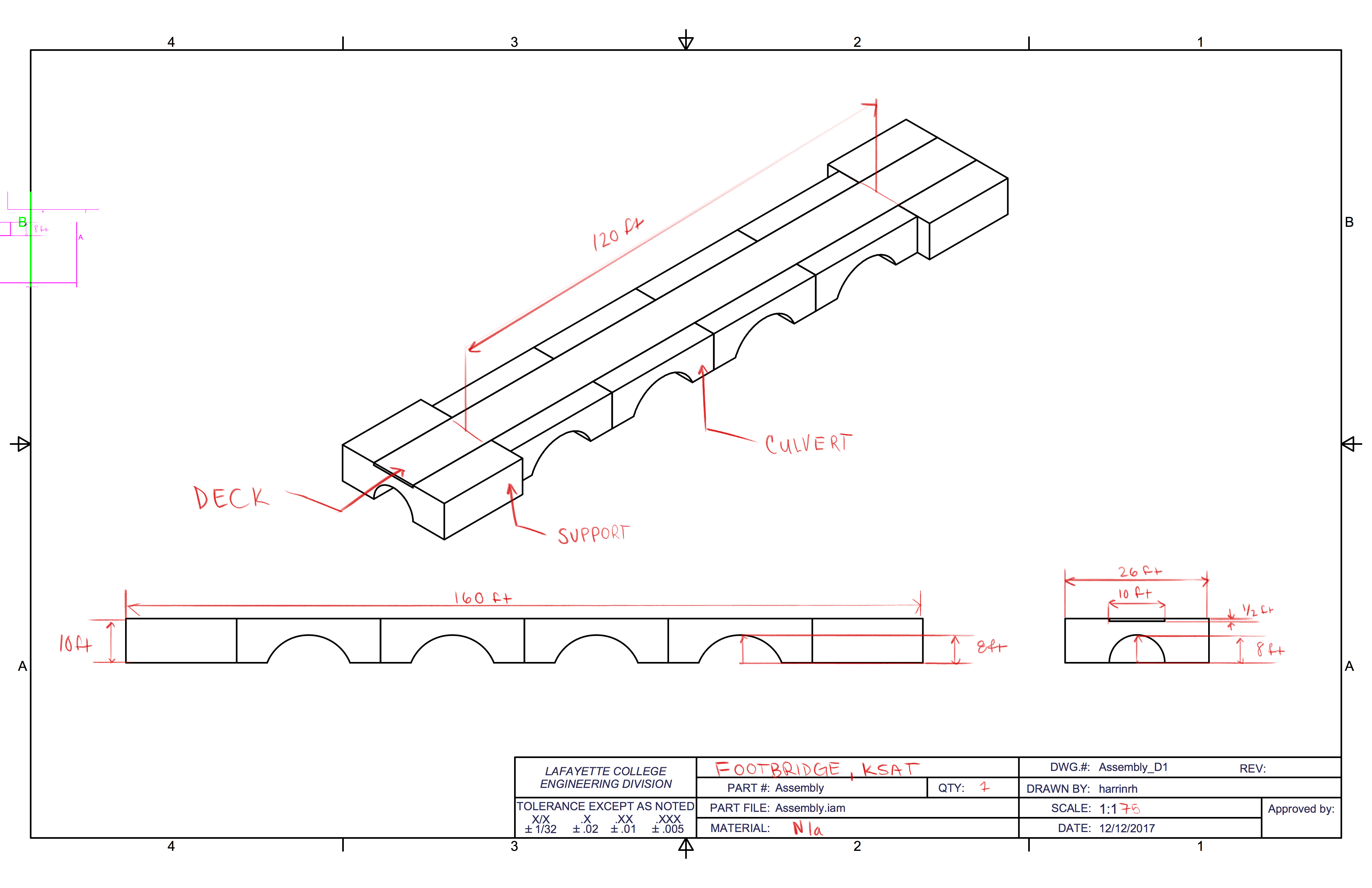
Figure 9: Inventor mock-up of KSAT bridge
The inventor model depicted in Figure 9 is supported by two precast concrete supports. These supports would ideally recede into the river bank and be less visible to onlookers. The model also includes four culverts used to support the deck throughout its 120 ft. span. These culverts feature a cylindrical cutout with an 8 ft. radius of clearance at the highest point. This 8 ft. clearance radius is taking into account FHWA regulations for weathering steel above running water such as the Bushkill creek (Federal Highway Administration, 1989). The deck model features a 120 ft. length over the creek itself, with a clearance of 20 ft. on either side to account for the supports. In return, this makes the total length of the bridge 160 ft. As stated before, the modeled deck is 10 feet wide to accommodate at least two people and meet federal regulation minimums.
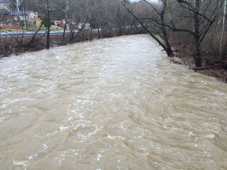
High waters at Bushkill Creek after heavy rain in February of 2016
In reality, the dimensions of this bridge may not completely reflect that of the Silk Mill bridge or this Inventor model because the KSAT footbridge aims to be more artistic rather than purely functional (Toia, 2017). Likely, artistic elements would increase or decrease certain physical dimensions depending on the final product. Additionally, the width of the footbridge may change depending upon the amount of projected traffic or alternative uses such as bicycles. The clearance height for the bridge will need to be analyzed by an engineering firm, specifically dependent on the materials interactions with the water as the Bushkill Creek is known to frequently flood. To address this, the mock-up inventor model allows future projects regarding this footbridge to experiment with different dimensions using the parameters function automatically. Additionally, it allows us to compare deflections and stress in different materials to better determine what works best for the KSAT bridge (Figures 10,11,12).
In terms of materials, our group researched three potential materials: steel, prestressed concrete, and fiber reinforced polymers (FRP). These materials were chosen because of their pervasive use in bridge building and their structural integrity associated with their material properties (Table 3). Each of these materials pose different benefits and disbenefits from a technical standpoint. In order to evaluate which materials are more suitable than others, we compared these materials on the basis of what best addresses the intention of this footbridge. Namely, sustainability, functionality, and durability.
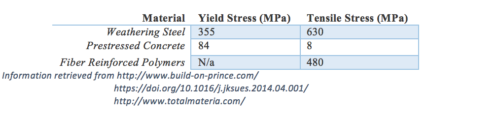
Table 3: Information retrieved from http://www.build-on-prince.com/
https://doi.org/10.1016/j.jksues.2014.04.001/
http://www.totalmateria.com/
Two of the most common materials used in bridge design are weathering steel (also known as corten steel) and prestressed concrete. It is a common misconception that concrete has a longer service life than steel due to the corrosive nature of metals. In actuality, steel and concrete have highly comparable service lives, and the deterioration of either material is more dependent on daily traffic and age (American Iron and Steel Institute, 2007). With this in mind, it may appear difficult to choose between the two as materials for a footbridge. Sustainability for steel is one of the highest for any construction material, as it is one of the most recycled materials in the world (>90%) (American Iron and Steel Institute, 2007). However, weathering steel is subject to several limitations by industry guidelines. The Federal Highway Administration (FHWA) urges caution when designing these bridges in certain environments and locations. Specifically, in environments with “Frequent High Rainfall, High Humidity or Persistent Fog” and locations “Eight feet or less over moving water (Federal Highway Administration, 1989).” Considering the fact that this footbridge is going to be located on the Bushkill Creek, and may be subject to high waters and flooding, weathering steel may not be a logical decision for the footbridge superstructure. An additional concern with weathering steel is the use of road salts to melt ice in the winter. Since the KSAT is open year round, it is likely that salts will be used to keep the trail ice-free. These salts can further corrode the steel superstructure in addition to the flood waters in the spring. Ultimately, a steel frame would be short lived and ill-advised (American Iron and Steel Institute, 2007).
Like weathering steel, Concrete superstructures may also be corroded by de-icing salts. Additionally, concrete bridges may be subject to freeze-thaw cracking damage that may compromise the structural integrity of the bridge itself. That being said, concrete is generally considered to be relatively a non-corrosive material and is often used as a primary resource in bridges located near or on bodies of water such as the Bushkill Creek. Concrete also has the added benefit of being able to take any mold or shape—an important consideration for the future artistic component in the KSAT. In terms of sustainability in comparison to steel, concrete requires significantly less energy than steel in production (Struble & Godfrey, 2004). However, concrete does not have the recyclability that steel possesses, putting the two more or less equal in terms of environmental impact.
FRPs are becoming an increasingly popular material in bridge construction. The lightweight nature of FRPs make them economically attractive in terms of transport costs in addition to being non-corrosive materials and extremely weather resistant. In comparison to prestressed concrete bridges, FRP’s may also be molded into any desired shape using heat. However, FRP superstructures typically have longer life cycles than concrete. Additionally, FRPs require less overall maintenance than any other bridge material (Nishizaki, Takeda, Ishizuka, & Shimomura, 2006). From a purely technical position, FRPs stand out as uniquely suited for a small scale footbridge project such as the one proposed. Nevertheless, the FRP industry is notoriously problematic when dealing with waste. In other words, although they may be sustainable in practice, the contingency plan detracts from its environmental friendliness. Often, FRP waste is disposed of in landfills, actively contributing to the negative environmental impact the KSAT and the Lafayette community abhor (Halliwell, 2016).
In addition to these comparisons, the materials can also be compared in terms of relative Von Mises stress. Von Mises stress is commonly used in the industry to determine whether or not structures will fail because it demonstrates the relationship between external loads and subsequent deformation. In this model, both the supports and the culverts are assumed to be fixed joints on surfaces connected to the ground and the bridge deck; these supports are expected to restrict motion in all directions. Assuming a 200lb person stands directly in the center of this bridge, we can examine the subsequent reaction each of the three materials might display. It is important to acknowledge that this singular point load is not representative of real-world conditions as a bridge may be subject to higher or lower point loads and likely multiple loads at a time. This model is simply a basis for different material reactions and may be altered when realistic foot traffic is determined.
Figure 10 shows how a steel deck may distribute a load across these supports, with a maximum Von Mises stress at about 0.00022 MPa. This number is minute and significantly under the critical stress for weathering steel shown in Table 3, indicating that this bridge would not fail under these conditions. Likewise, Figure 11 shows a concrete deck under the same loading conditions, resulting in a maximum Von Mises stress of .00021 MPa. Although this maximum is highly comparable to steel, it is important to note that the scale for steel runs slightly higher than the scale for concrete. This indicates that a concrete deck may handle additional loads marginally better than a steel deck. Finally, the FRP bridge depicted in Figure 12 shows the highest maximum Von Mises stress out of all three at .00082 MPa under similar loading conditions. Although of these potential stresses are well below the yield stresses of each material featured in Table 3, this analysis provides us with another material property consideration when designing this footbridge, or how loading conditions affect potential stresses within materials. Inventor is set up with several different materials outside of the ones examined in this report, as well as the ability to change the force on the load and the location. Future projects are encouraged to examine additional materials and loadings to best estimate what material would be suitable for the KSAT bridge and the traffic it may bring.
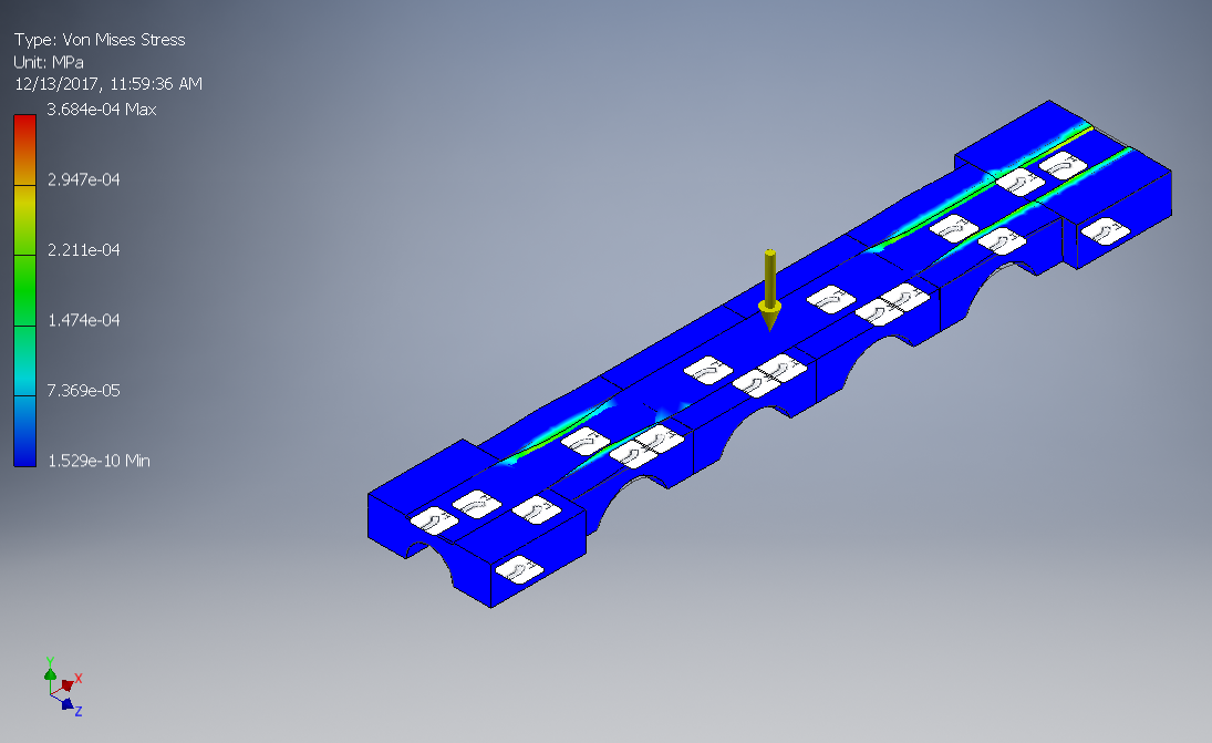
Figure 10: Von Mises stress over steel deck
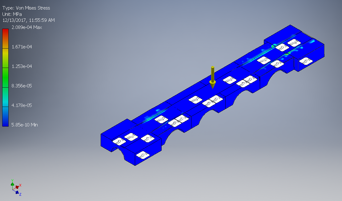
Figure 11: Von Mises stress over concrete deck
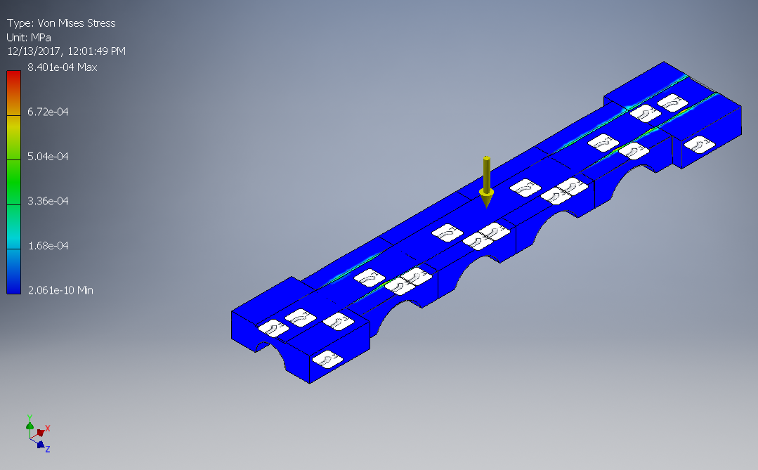
Figure 12: Von Mises stress over FRP deck
Though our group cannot make any final decisions on materials, our report synthesizes information so that a future entity may be able to make an informed decision regarding the technical details of such a footbridge. Subsequently, our group, after preliminary research, recommends that concrete or FRPs would be the most suitable for the KSAT, instead Corten steel due to FHWA regulations. However, external factors such as cost may also play into recommendations featured in the economic section of this report. Future projects are encouraged to advance this research by applying professional opinions to this rough data to create a more precise outline of the actual footbridge.