PACMAN Repository
All development work on the PACMAN system, both software and hardware, should be done in the BitBucket Repository.
If you need assistance getting access to this repository, contact John Gehrig
Hardware Design
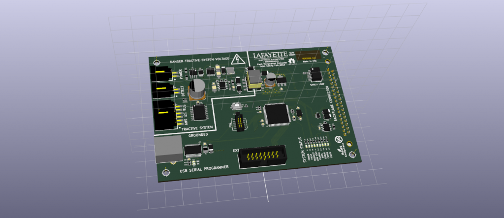
The hardware was designed with two primary considerations: simplifying pack wiring, and solving the voltage isolation issue. The design minimizes HV/LV interfaces, while delivering up to ~6W of isolated 5V power from the battery pack terminals. This allows the processor to easily communicate with low voltage systems. The device also employs a DB-37 connector to simplify and clarify pack wiring. As the design progresses, a “wiring harness” should become a documented and itemized part of the battery pack.
Application notes are contained within the schematic. All parts numbers, and data sheets are contained within the schematic, click “Edit Component” to access them.
PACMAN Hardware Files
All files to reproduce and extend the hardware design are listed below.
- Schematic (PDF) (Rev 0.3)
- PCB Reference (PDF) (Rev 0.3)
- Digi-Key Order (PDF) (Rev 0.3)
- PACMAN BOM (PDF) (Rev 0.3)
- KiCad Project (ZIP) (Rev 0.3)
- GERBER Files (ZIP) (Rev 0.3)
- 3D VRML Model (ZIP) (Rev 0.3)
Hardware Errata Documentation
Here are the known design short-comings as of Fall 2015.
Delivered Hardware Notes
The delivered hardware suffered a failure of the high side 5V buck converter. Before this failure the system was functional, however voltage spike destroyed components within the system including: i2c-transceivers, can-transceivers, ams power, and the i2c-adc. Some of these components have been replaced, but if you are using this system for software development, judge accordingly. All low-voltage electronics appear to be functional again.
Software Design
The PACMAN software is a RTOS (Real Time Operating System) running on an 8-bit AVR microcontroller. It is capable of sending/receiving I2C packets, CAN frames and writing to a character LCD.
PACMAN Software Files
- PACMAN Software Repository (BitBucket)
- PACMAN Programming Manual (PDF)
- PACMAN Build Environment (Google Drive)
Software Errata Notes
Software development efforts were incomplete, more work will be required to get the system functional. A solid foundation framework has been provided for dealing with the AVR hardware, including: GPIO, I2C, and CAN. An RTOS and task structure are also provided with the system.
Work still needs to be done for Control Algorithms, Safety Monitoring, and GUI.
SocketCAN Linux Notes
The protocol for CAN used by the LFEV is a request and response framework. The SCADA system should send a remote transmit request to each node on the bus when it requires data from that node. The node will respond with one or more data frames consisting of 8 bytes each.
To bring a test virtual CAN environment up:
$ modprobe vcan
$ sudo ip link add dev vcan0 type vcan
$ sudo ip link set up vcan0
$ ip link show vcan0
To bring a “real” CAN network up:
$ sudo ip link set can0 up type can bitrate 250000
$ sudo ip link set can0 up
The package can-utils is useful for monitoring and debugging traffic on the CAN bus. Download the can-utils package if your distro provides it.
See the man pages for candump & cansend for more details. Linux CAN Utilities