Week 4

Nick designed and laid out a protoboard for the player module and then spent 10 hours soldering it together.  We decided that soldering more modules would not be an efficient use of our time, which leaves us with only two player modules. Nick also added negative number functionality to the player module. He also drew a schematic of the player module.

Brandon added functional start and reset buttons to the host module and removed extraneous information about the touch screen from its display. He also fixed several small outstanding bugs with the interface and brought negative number functionality to the host module.

The large majority of the remaining work was done by both Nick and Brandon working together to troubleshoot issues.

The new set of Bluetooth chips arrived this week.  We assembled them and were able to successfully connect and communicate over them.  The host module is controlled via HCI protocols, meaning the host module needed to send, receive, and interpret specific op-code commands over the UART.  Although we had the basis of a library for this, there was a significant amount of converting and additional code required before we could use it on the PIC.  A major hurdle we had to overcome was that some of the op-codes contained special and reserved characters, such as line feed (\n, 0x0A) and carriage return (\r, 0x0D), which prevented directly printing the op-codes.  We ended up bypassing pt_cornell_1_2.h and writing our own UART print using functions from uart.h.

Communication from the host module to the player module works well, but only when the target player module address was hard-coded into host module.  We had an absurd amount of difficulty in trying to read from the player modules to the host module.  The correct data was confirmed to be showing up on the RX pin into the PIC, but the onboard UART module failed us.  We spent over 40 hours over the past four days trying to get just this functionality working.  By jury-rigging an error check accounting for overrun errors to also poll a value from a specific location in PT_term_buffer, we were able to get it about 70% working 30% of the time.

After a some research we came to the conclusion that the combination of Protothreads and the PIC itself makes reading the particular piece of data we care about out of the notification messages from our central Bluetooth (Low Energy) chip is exceptionally difficult.  An overrun error is when the UART receives new data before the old data is completely read.  When the error occurs, it throws a flag that locks up the receiver and prevents any further data from being read in.  Receiving large amounts of data at any baud rate very quickly will throw an overrun error and this was thrown when receiving data from the BLE chip and also when receiving multi-character data from the PC terminal.  We tried several ways to fix this like manually clearing the error flag and trying to salvage what was in the buffer when it was thrown.  Another way was to write our own UART read function to make sure we weren’t jumping to random places in the middle of our read to hopefully avoid the overrun error, but we had still had similar problems with freezing up mid-receive.  Ultimately, time became a factor and we abandoned the attempt.

As such, we are implementing a Plan B, which while significantly less complex, should also be achievable by Tuesday morning.  This Plan B is to have the host (the person, not the module) pick which player buzzed in first by eye (based on when the buzzers light up) and select that player on the LCD touch screen, which well turn off the other players’ lights and set the target module address in the software.  Nick modified the player module code for Plan B.  Brandon modified the host module code.

Week 3

Our goal for last week was to make progress on the software side of our project including the Laser Triggering setup, the LCD outputs and the Motion Sensor control operational. We also aimed to get significant work done on the Motion Sensor setup that will be used to monitor individuals at tables. In addition, we ran into some problems with the photo-detector output current we had to fix.

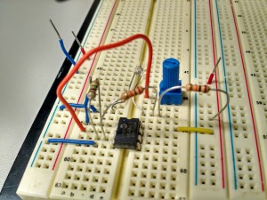
  • The photo-detector we were using for our Lasor Link was outputting currents that were not allowable by the PIC, to fix this, we used the same MCP6242 Op-Amp setup used in Lab 5. A picture of the setup follows below.

IMG_20151201_031812Our second task this week was the software side of our project. The following tasks were achieved in regards to this.

  • Configured Timer for Photo-transistor interrupts
  • Configured input capture & interrupts for Photo-transistor input. We are now able to determine if a person just entered the room or left.
  • Configured motion sensor input to the PIC and the timer. If any motion has been detected around the seat we are monitoring within the last 5 minutes, we can conclude that that seat is occupied.
  • Configured various proto-threads
  • Configured LCD to display the current number of people in the room.

Our plans for next week are as follows.

  • Obtain a stable mount for the laser link
  • Tune sensitivity of the motion sensor
  • Finalize table occupancy graphics on LCD
  • Obtain motion sensor mounts


Week 3 Status -phil

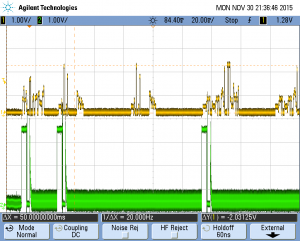
As scheduled, work was done on sound production this week. The objective was to read data from the SD to get buffered data and write to the DAC simultaneously using DMA with previously buffered data. A basic implementation was achieved this week, but we have been plagued by bugs. Notably the DMA transfer occurs twice for some unknown reason.

I am definitely behind schedule as sound production was supposed to be done this week. Hopefully a breakthrough can be made within the next couple of days.

test_rep

DAC output on top and SD card output on bottom. After the first cycle data repeats twice.

Status Report Week 3- Joe

Much progress has been made since last week as far as the fingerprint scanner. Last Tuesday in lab, it was discovered that the assumed wiring of the scanner was incorrect. The correct wiring has been determined. Much time was spent attempting to get UART communication working between the fingerprint scanner and the PIC. It was discovered that the wire which is being used to connect the fingerprint scanner to the breadboard was preventing transmission from the fingerprint scanner to the pic from being received. When held in the right orientation, the fingerprint scanner was able to receive the 12 byte command packet and return a 12 byte response packet as well as a data packet when necessary. I was able to implement both an open command as well as turn on the blue LED in the fingerprint scanner. Now that the communication protocol has been worked out, I will code up a library of functions for the fingerprint scanner to perform the designated functionality as well as find a better way to connect the wires on the fingerprint scanner in order to prevent the PIC from missing transmissions. The fingerprint scanner will be combined with the SD card reader which will be able to play different tones based on the person who rings the doorbell.

Week 3- Austin

Interface!

Over break (in between stuffing my face with food), my goal was to design an interactive interface for our system. Unfortunately, I forgot my computer charger and was unable to. BUT I came back and worked on it, initially coming up with a state machine that I would then implement. This iteration of the interface will have a ‘Main Menu’ that has buttons that lead the user to three other menus: Enroll, View History, and View Enrollments. The state machine can be seen in the link below.

Interface State Diagram

The code is not fully implemented yet, but will be by the end of lab period tomorrow (unless we focus more on the fingerprint scanner).


Goals for this coming week: get the Fingerprint Scanner working.

This is the main goal for Joe and I this week.

Week 3 Status Update

Our primary goals for this week were to further implement the EEG reading systems, fully get the real-time clock and alarm clock controls implemented and also begin setting up the audio system of the alarm. We had difficulty accomplishing all these goals mostly due to being away for Thanksgiving break however we did managed to get some things accomplished.

Kyle primarily worked on the EEG portion of the system again. Since we were having difficulties implementing the EEG reading last week, we did a sanity check with the headset using the chipKit UNO 32 board. This source code we are using to base our code off of was originally meant for use on this type of board. We were able to the EEG reading fully working on this board. We also tested the reading using the computer Putty terminal. The text read by UART using this was unintelligible however it was being read once per second. Trying to again implement the UART reading on the PIC32 we were having issues reading the UART register. We are able to get 9 readings off of it and then the program freezes, however we do seem to be reading the correct integer values.

Rich primarily worked on the clock portion of the project again. We were able to get the set real-time clock functionality working and was able to implement the set alarm time functionality working. We were also able to get the alarm control system working and all that is needed now in that portion of the project is to add the audio to go off when the alarm is triggered. We are almost done on the actual digital alarm clock portion of the system. It should be easily accomplished.

The main challenge right now is the EEG readings. We will need to consult our lab instructor in order to figure out our issues with UART as we feel it is majorly blocking necessary progress.