Our goal for last week was to make progress on the software side of our project including the Laser Triggering setup, the LCD outputs and the Motion Sensor control operational. We also aimed to get significant work done on the Motion Sensor setup that will be used to monitor individuals at tables. In addition, we ran into some problems with the photo-detector output current we had to fix.
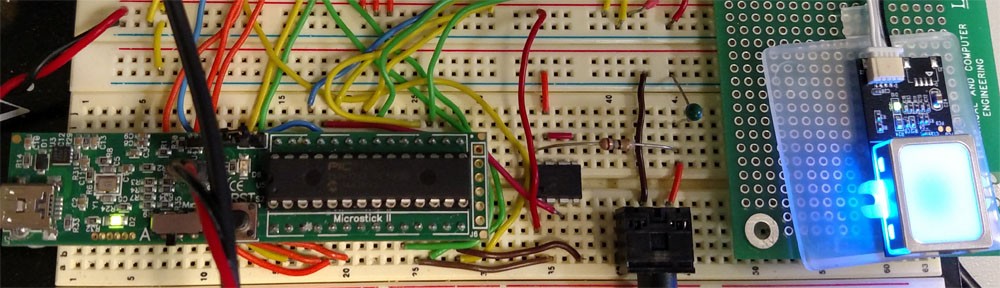
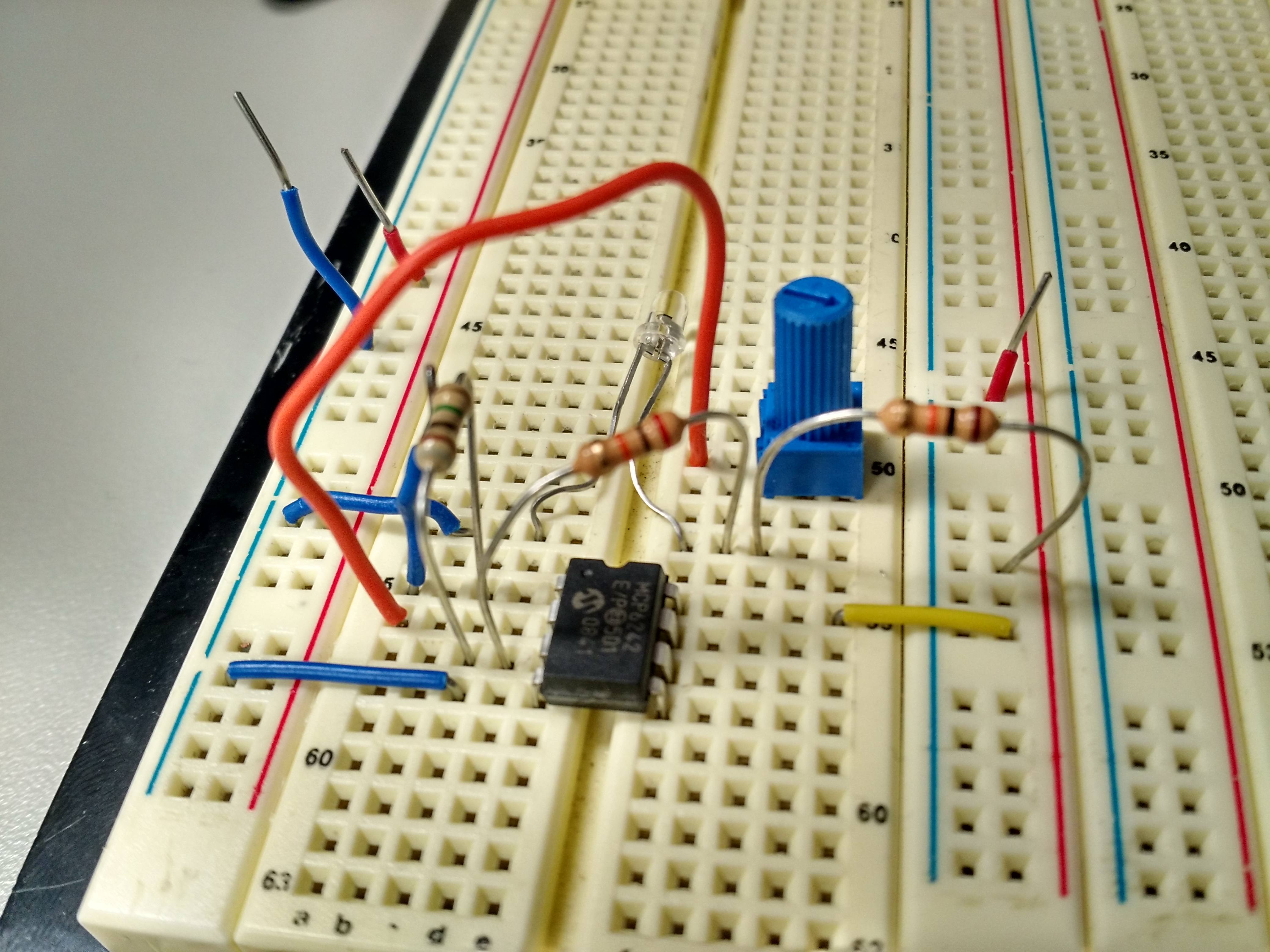
- The photo-detector we were using for our Lasor Link was outputting currents that were not allowable by the PIC, to fix this, we used the same MCP6242 Op-Amp setup used in Lab 5. A picture of the setup follows below.
 Our second task this week was the software side of our project. The following tasks were achieved in regards to this.
- Configured Timer for Photo-transistor interrupts
- Configured input capture & interrupts for Photo-transistor input. We are now able to determine if a person just entered the room or left.
- Configured motion sensor input to the PIC and the timer. If any motion has been detected around the seat we are monitoring within the last 5 minutes, we can conclude that that seat is occupied.
- Configured various proto-threads
- Configured LCD to display the current number of people in the room.
Our plans for next week are as follows.
- Obtain a stable mount for the laser link
- Tune sensitivity of the motion sensor
- Finalize table occupancy graphics on LCD
- Obtain motion sensor mounts