Operation
The Laser Link Body Count system was responsible for monitoring the number of people at any specific point in time at any dining hall employing our system. It uses an ingenious combination of lasers and photoreceptors, two of each, to achieve this, placed one in front of the other. Each laser would be met on the other side by a phototransistor, both placed on one side of monitored dining halls. As people walked into a hall, they would trip the laser, then the other laser. Our microcontroller would record the time at which these two actions occurred and preform some simple algebra to figure out if a person was leaving or not.
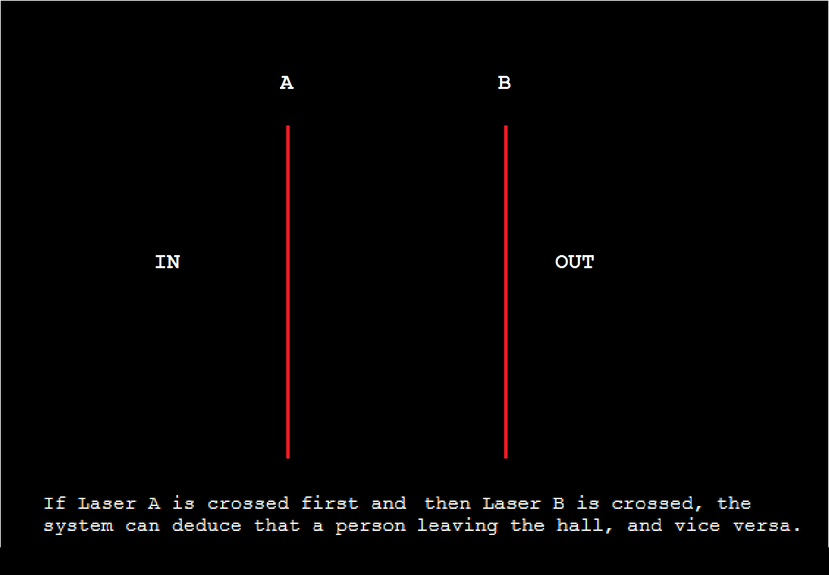
- The Laser Link would be placed at least at waist height to make sure people trip the lasers as they walk in and also avoid inaccurate readings from lasers being tripped by two legs from the same person.
Setup and Design
Lasers
The lasers we used were provided by our very own Professor Nadovich instead of the purchases we had already planned. They were the very ones the school used for its audio over laser projects. Setup was achieved through the use of an external 9V battery scaled down to the required value. Though the lasers could have been powered with voltage from our microcontroller, the use of external sources was a design choice we made after consideration of the distance that needed to exist between them and the phototransistors. After getting them setup, we were ready to proceed with the phototransistors.
Laser : Front View
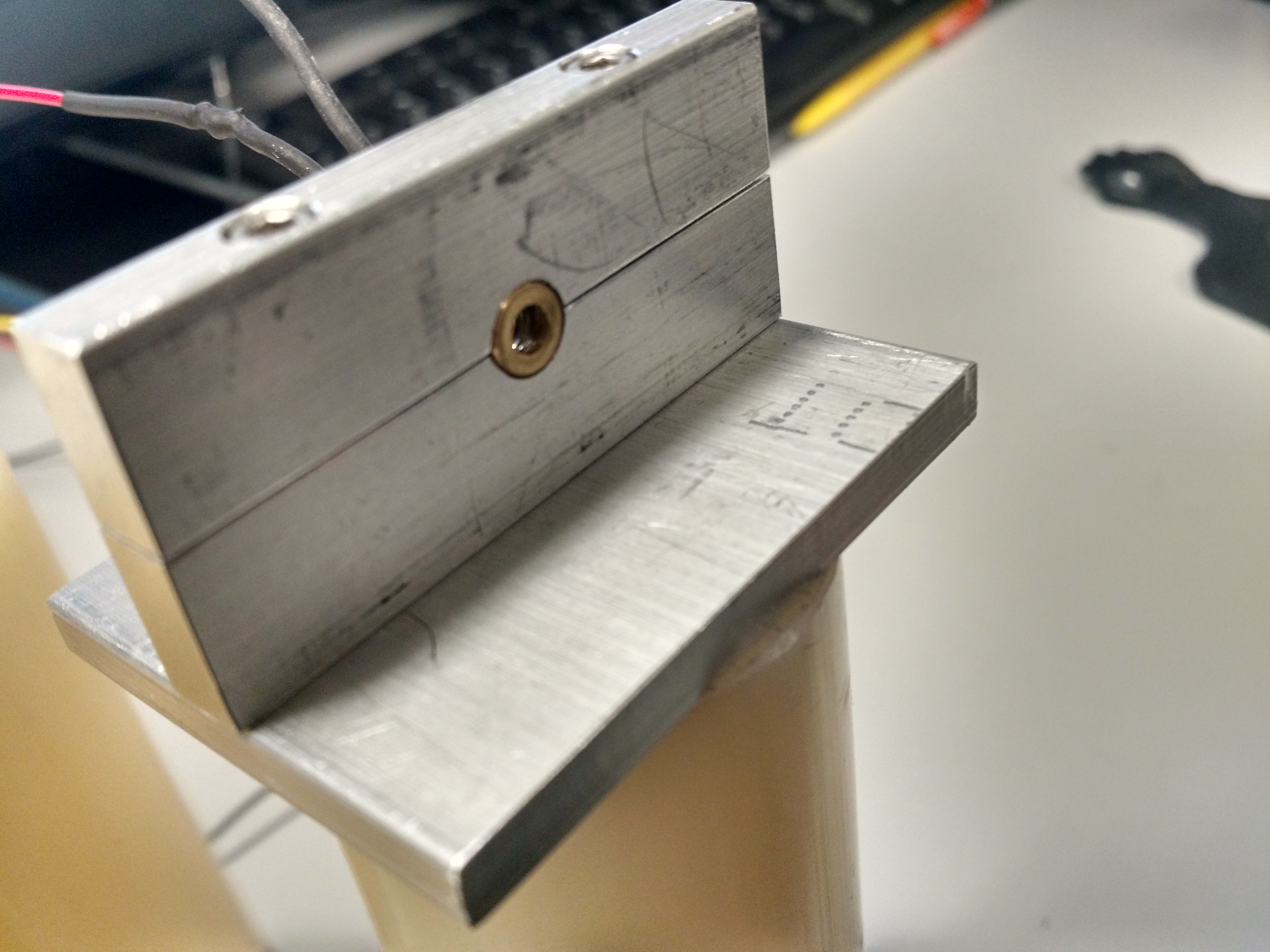
Laser : Back View, alterations made are visible, including altered wiring.
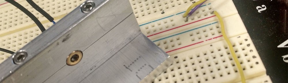
Through very fortuitous, the lasers we acquired were not without their problems. The default wires were very weak, short, frayed, and much too weak to even penetrate our breadboard let alone hold up the relatively heavy lasers; and as such, made testing a right pain. We had to custom-make stands for them through the school hardware shop, and make sure to add extra wire to increase length and use some heat-shrink tubing to enhance their durability. A visual of the modded lasers as well as the accompanying circuit can be seen below.
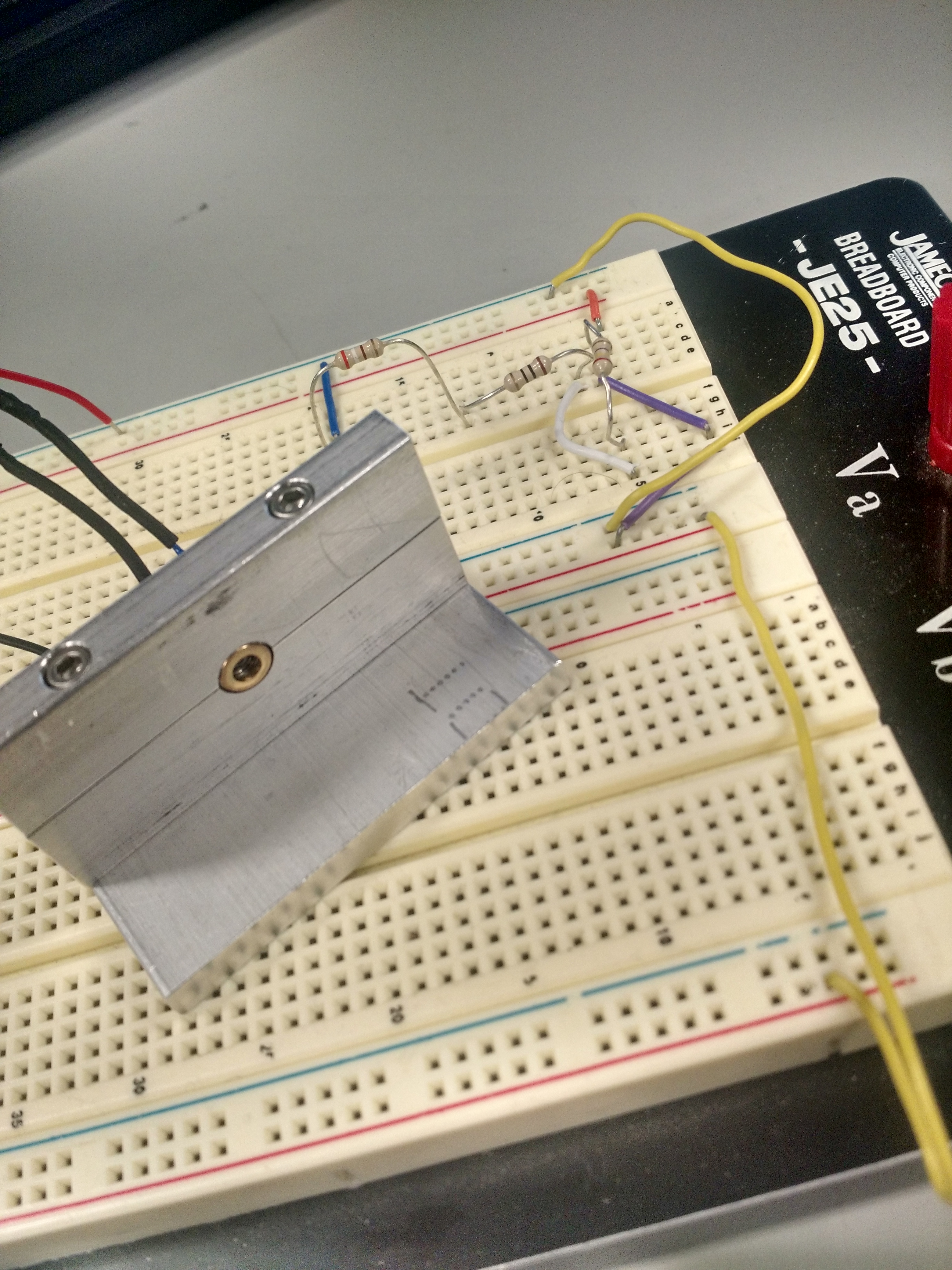
Laser with Accompanying Circuit
Phototransistors
We were also given some phototransistors to work with by Professor Nadovich. These served as the other half to the system by detecting the lasers and sensing when they were tripped. They ran on power supplies in the range of 1.8V to 5.5V, which could easily be supplied by our microcontroller. When not detecting the phototransistors defaulted to outputting 0V, and output a voltage of 3.3V when detecting the lasers. Setup of the phototransistors included the use of an MCP6242 op-amp comparator for getting more precise outputs for aid in calculations.
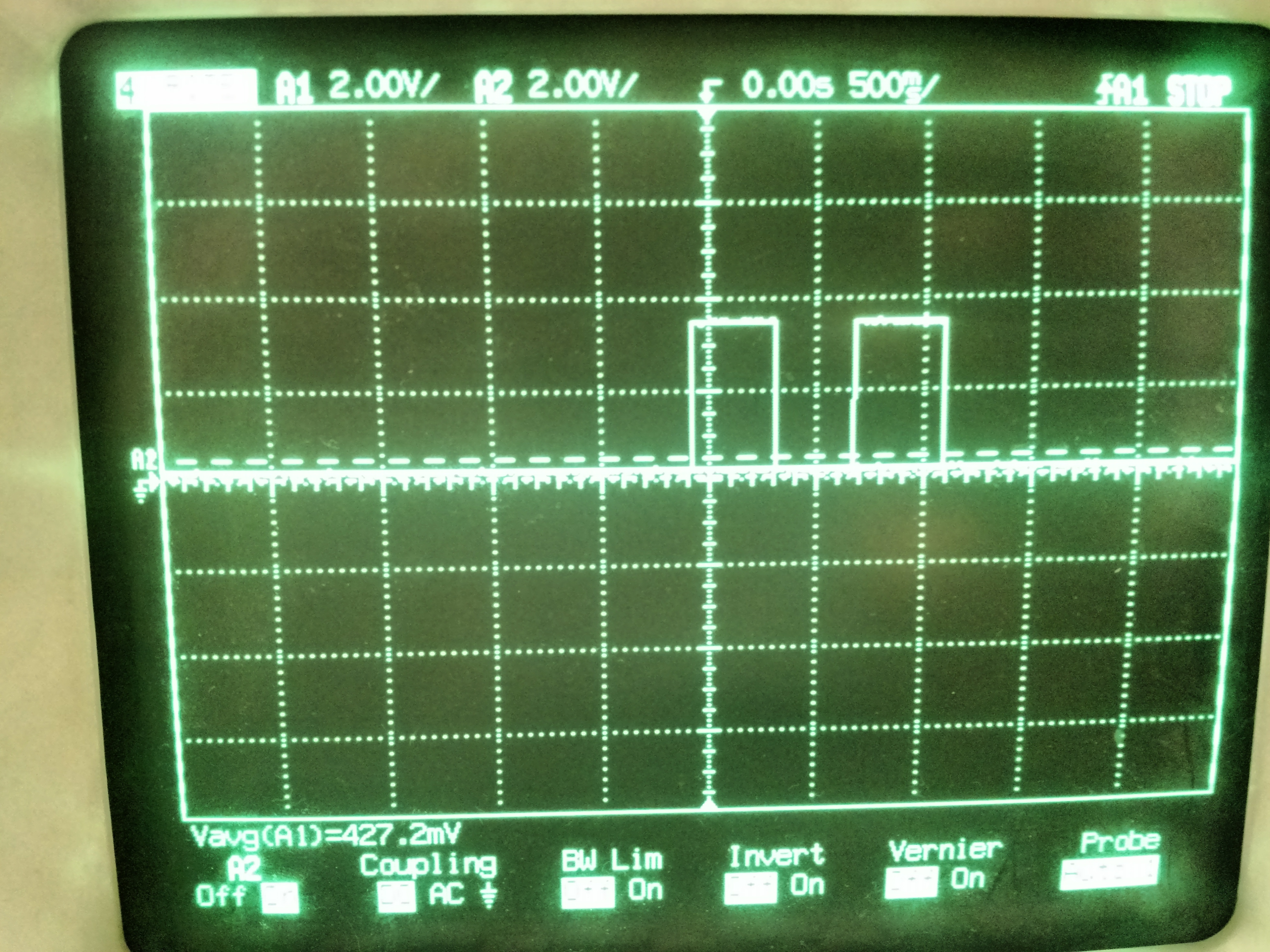
After setup was completed, testing was relatively straight-forward. We monitored the photo receptor output voltage from the phototransistors through oscilloscope to make sure expected operation was achieved and verified that it was. The scope-capture below shows our two phototransistors tripped one after another; each outputting a voltage of 3.3V for the duration and returning their default 0V output after.