The overall schematic for our system is shown below. We apologize for the large image. Please click on it if you wish to see a more detailed view. 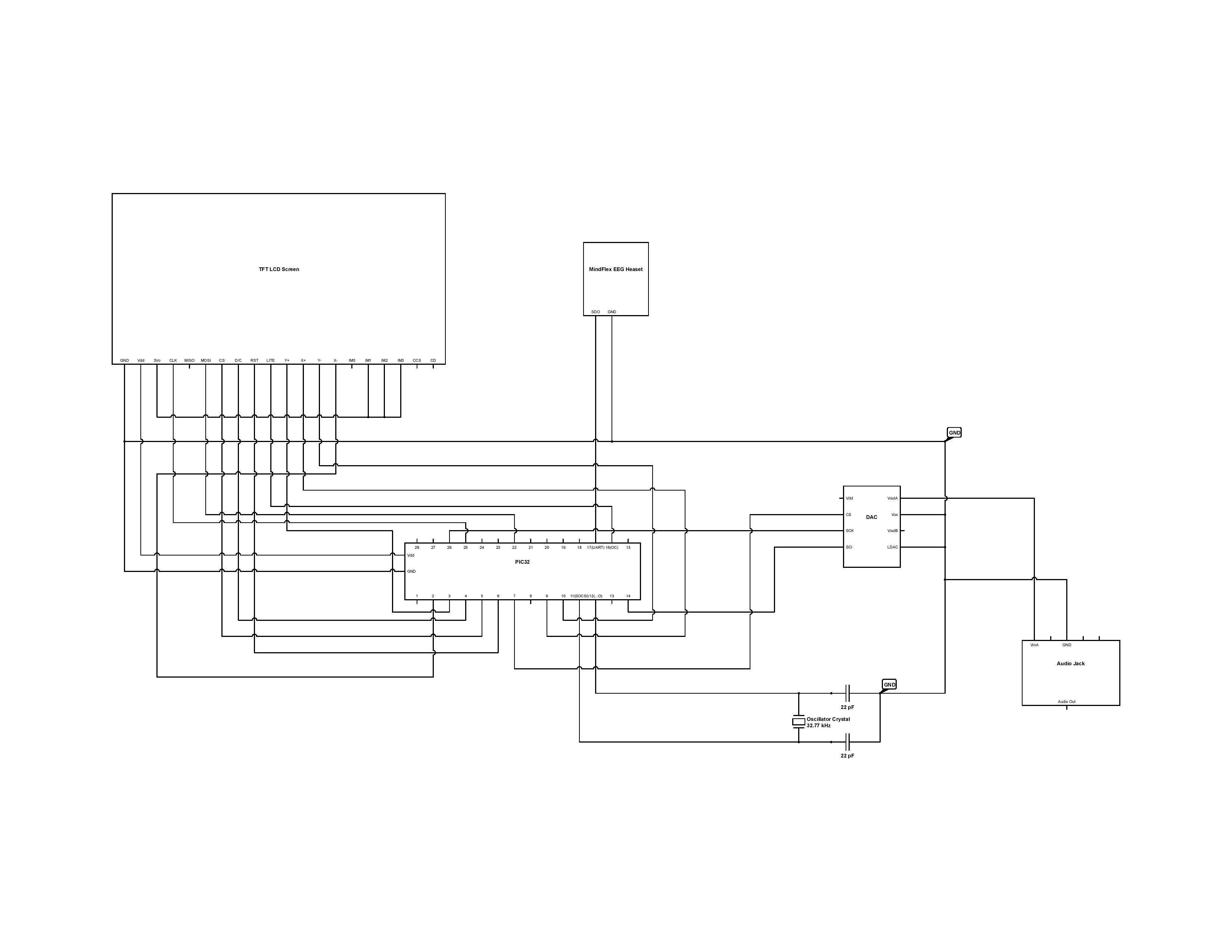
Parts List
- PIC32MX250F128B, $4, In house
- Adafruit TFT LCD screen with touch screen, $28, In house
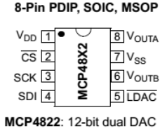
- 12bit DAC (MCP4822), $3, In house
- Breadboard audio jack, $1, In house
- Hytobi Speakers, $8, In house
- 32768HZ Crystal Oscillator 2 x 6 mm, $1 for 10, In House
- MindFlex Headset, $24, Ebay
MindFlex Headset
The MindFlex EEG headset was the sensor we chose to use for acquiring EEG data. The MindFlex headset is actually used as a part for a game developed by Mattel toys where a user attempts to control a ball with their mind. However, the headsets themselves can be bought separately and hacked. If a few connections are soldered to the TGAM1 board in the MindFlex headset, the data that is usually used by the MindFlex game can be read using UART communication protocol. The TGAM1 board is the same board used in another higher quality EEG headset created by the company NeuroSky thus we believed it to be of relatively high quality as well.The TGAM1 board sends out a data packet once every second as serial data. We followed directions we found on many online forums to make the connections from the board to the PIC32. 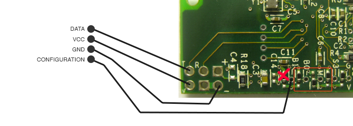
We simply soldered one conncection onto the T pin shown above (given the label DATA) and connection to the (-) pin shown on the board (given the label GND). The connection on the T pin was the data line and the GND connection was obviously the GND line. We then attached the data line to a pin we designated to be a UART RX pin on the PIC32 and attached the GND line to GND on the PIC32. This is the hardware portion of the EEG Reading sub-system of our design. Below see an example of the headset being worn by a user. 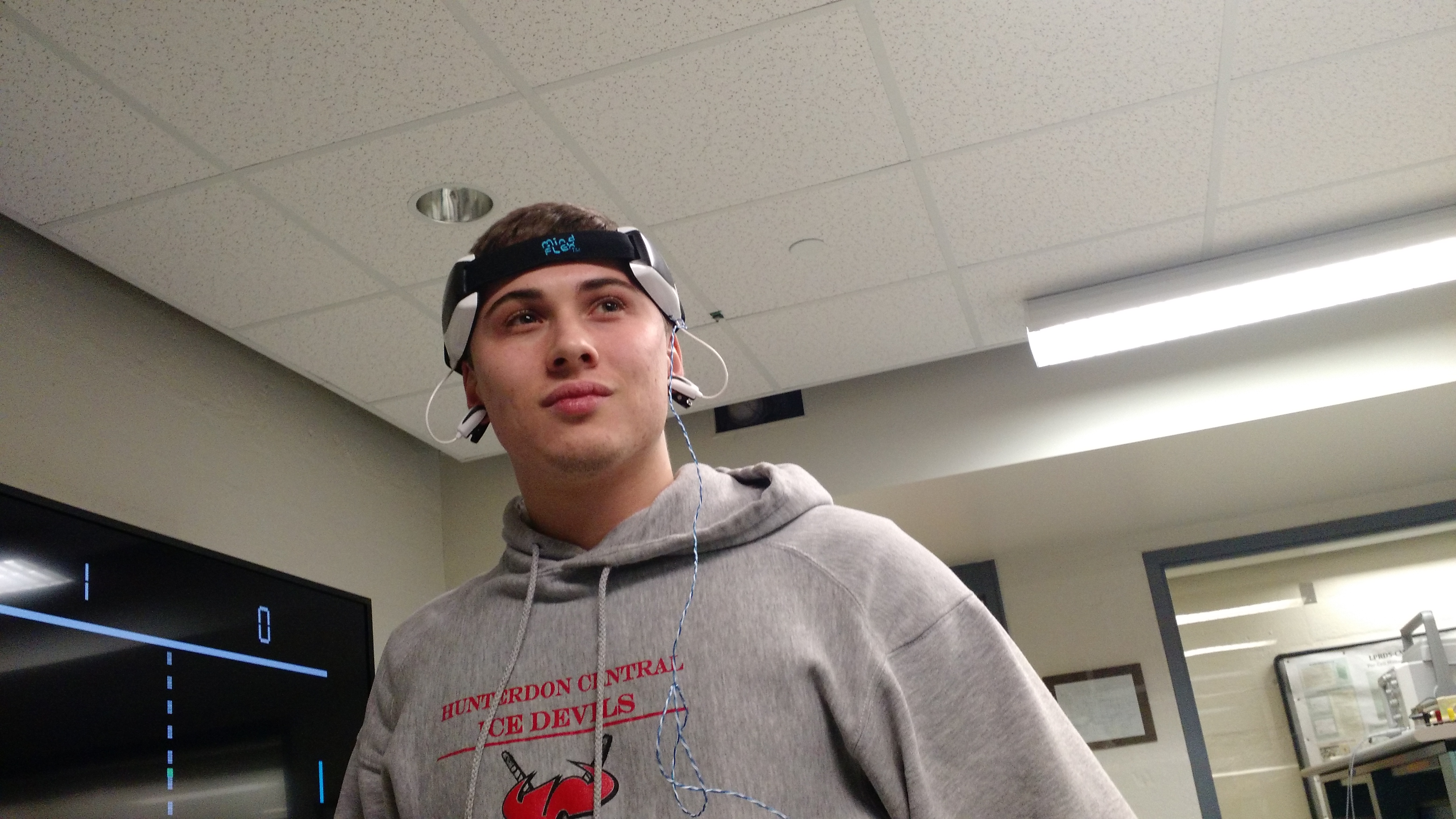
PIC32 Peripherals
One of the only PIC32 hardware peripherals we used was the Output Compare peripheral. The Output Compare was configured to generate a PWM signal to be sent to the LCD touch screen to control dimming of the screen.
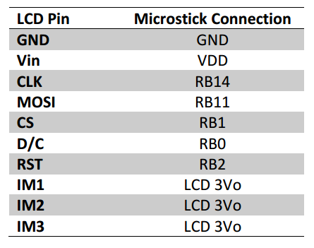
LCD TFT Touch Screen
The LCD touch screen was from the Adafruit webpage. We have used this screen in almost every one of our labs and is used with supporting TFT libraries. For this system, we hooked up the screen using the connections shown in the diagram below:
Secondary Crystal Oscillator
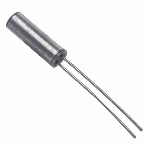
In order to run the Real Time Clock on board the PIC32, an external oscillator is required. For our system, we were given an external oscillator by our lab instructor. Above is a picture of this oscillator. The external oscillator was a crystal that oscillated at 32768HZ. The hardware setup for the oscillator was relatively simple. The crystal requires 22pF capacitors on each of its lead’s tied to ground and then one lead connected into the SOCSI and the other lead connected into the SOCSO on the PIC32. SOCSI stands for Secondary Oscillator Input and SOCSO stands for Secondary Oscillator Output. A schematic for the setup is show below. 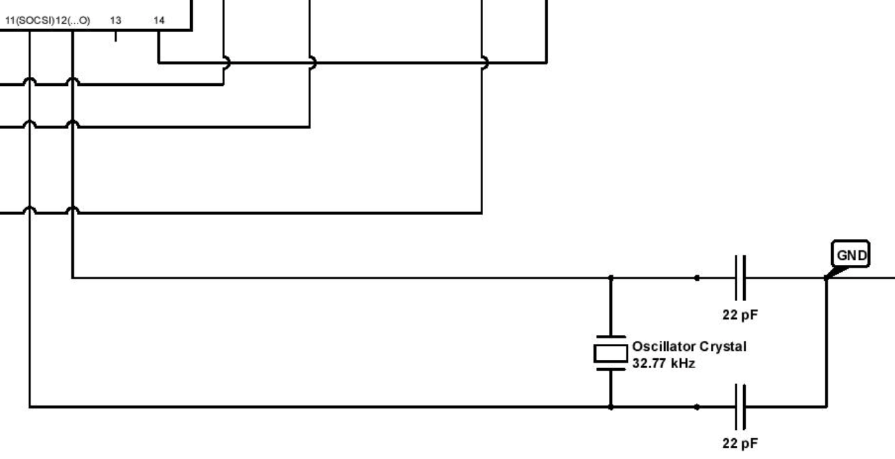
Audio Output
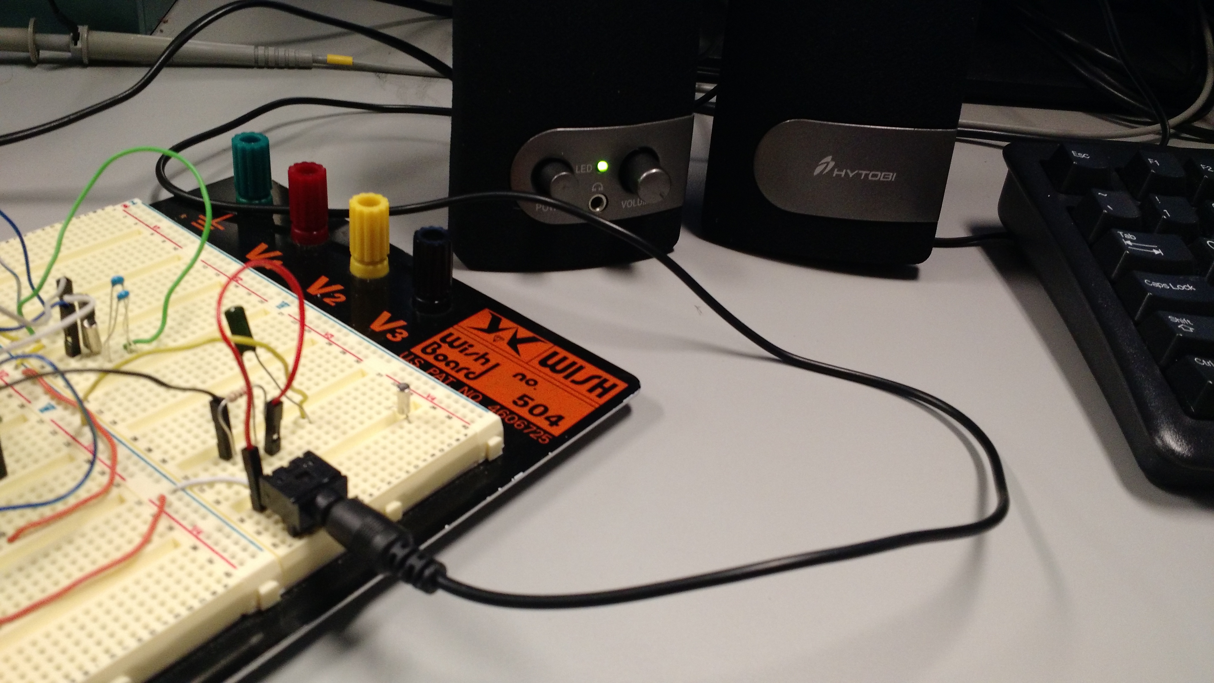
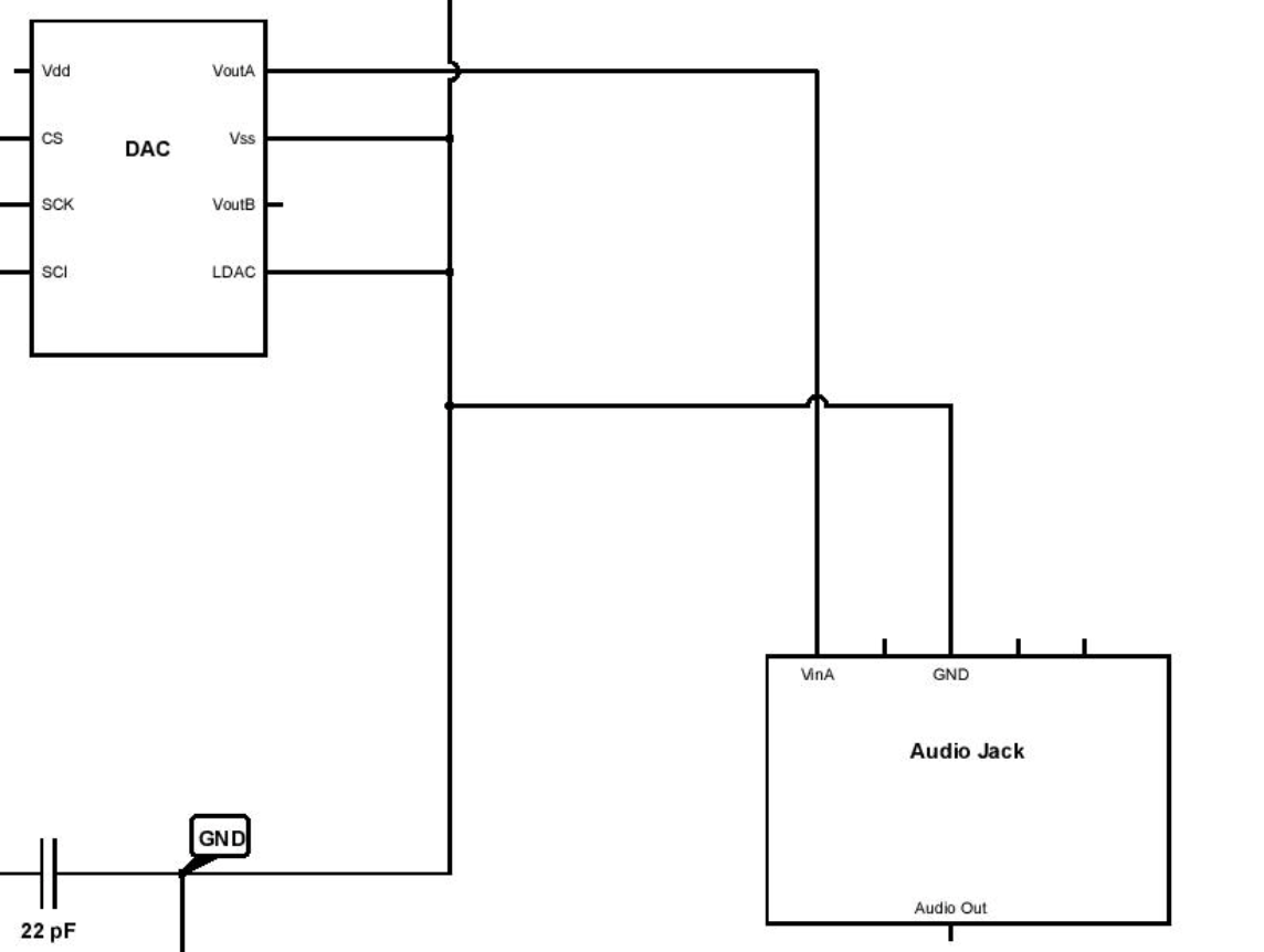
Above are the speakers we used, connected to our system. The audio output accomplished was done through relatively simply means. In software, digital values for a sine wave were generated via Direct Digital Synthesis and then sent to the MCP4822 Digital to Analog Converter via SPI communication protocol. These values were only sent to the DAC when the alarm was triggered. The DAC then generated an audio signal which was sent to a 8th inch audio jack and then to the Hytobi Speakers. The connections for the DAC are shown below to the left and the overall schematic is shown below to the right.
Page Directory