
Overall Design
For the software aspect of our design everything was coded in C into one file using MPLAB IDE. In the file we used a threading supporting library to manage our processes. All of the process in our system were done using a thread or an interrupt. The threads we used are listed below:
- Clock Display- controls display of clock
- Point Getter- reads touch screen controls
- RTC Config- manages calibration of the clock
- Alarm Control- manages the alarm system
Real Time Clock
We used the RTC functions on the PIC32 as it would provide us an accurate timer so that we would have an alarm clock that would actually be functional in the real world. It also has its own internal alarm interrupt that we could have decided to use if we didn’t also want to implement the EEG readings into our system.
The real time clock system is configured by having a 32.7kHz oscillator crystal series with two 22pF capacitors in parallel. This would allow the oscillator to give pulses to the PIC32 every half second which would allow it to count time up correctly.
The real time clock is set by feeding a string of integers into the BCD using the set time function. This string is required to be in hexadecimal format with all of the integers being in BCD. For example, if you wanted to have the real time clock set to 2:33;55PM you would have to give the function the input (0x14335500).
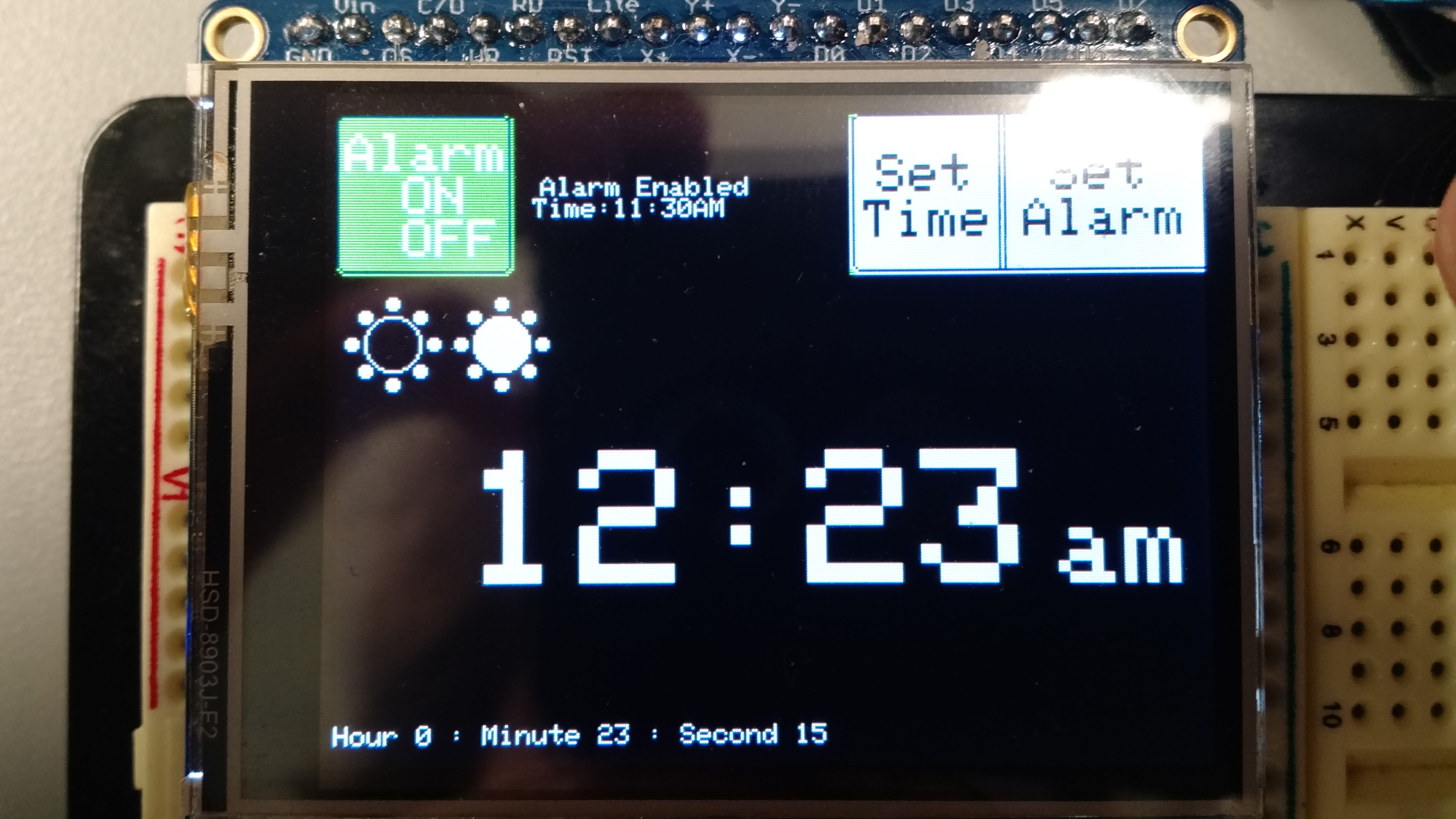
We displayed the real time clock variables by using the realTimeClock sec, min, and hour variables that are readily accessible and are the current BCD encoded values of the current time. We would convert these BCD values into regular integer values then we would use print statements to show those values on the screen.
The parts that were definitely tricky to write had to deal with the real time clock. To be able to set the real time clock you had to give it a string which would be comprised of integers which it would parse to different registers to set the values on the clock and alarm. It also expected that this string would be in BCD format so we had to convert our integer values into BCD format, convert those BCD integers to strings and then concatenate the different strings into one large string which we could feed to the real time clock.
EEG Reading
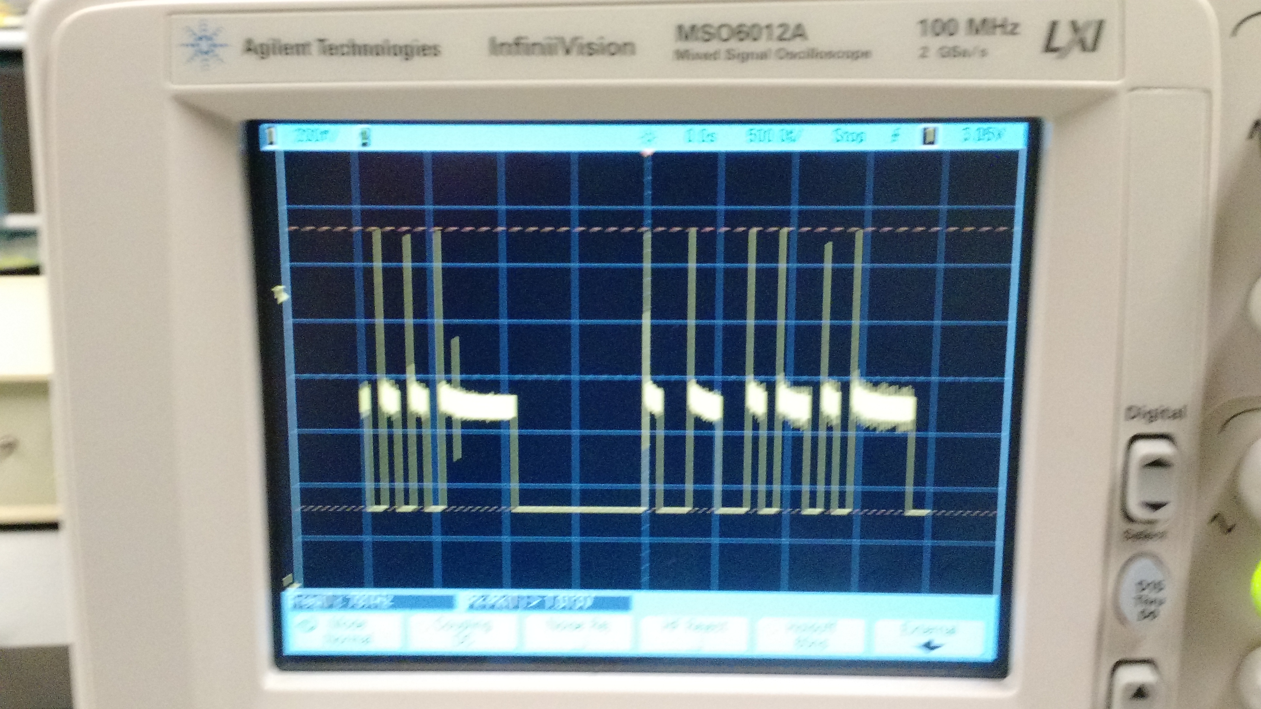
The EEG reading was implemented in software by using the PIC32’s UART functionality. An important factor in implementing the EEG reading sub-system was the format of the data packets sent from the TGAM1 chip aboard the headset. The data packets were sent once every second as serial data and contained a series of integer values along with start/stop bits and a checksum bit. Below is an oscilloscope image of a portion of the data packets.
Data Packet Format — [signal_quality, attention, meditation, deltaBand, thetaBand, lowAlpha, highAlpha, lowBeta, highBeta, lowGamma, highGamma]
Above is the data packet format. The first value indicates signal quality and is an integer value from 0-200, which 0 being best signal quality and 200 being worst signal quality. The second and third value, attention and meditation, are values calculated on board the TGAM1 chip and are values ranging from 0-256. The next 8 values are different frequency bands read from the chip and range from 0-2^(32). Below shows which names correspond to which frequency range. 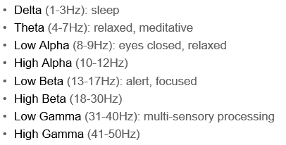
In order to read the data, we needed to configure the UART peripheral correctly. The UART peripheral was configured to read 8-bit data with one stop bit. We also configured an interrupt to be thrown every time something was put into the FIFO buffer in the UART peripheral. In the ISR for this peripheral is where we read the UART data. We based our code in this ISR off the code in the Brain Arduino project linked here. One important aspect of the ISR is that we clear the Overrun Error bit in the UxSTA register every time it is called to clear the buffer so that it does not get filled up. We had a lot of issues with this initially as the full data packet is much larger than the FIFO buffer. Therefore we would get the end of the data packet cut off since the buffer would fill up and then throw out the rest of the data. Using these methods we were able to get the data packet correctly. We then parsed the data packet and printed it to the LCD screen using methods found in the Brain Arduino project as well.
Sleep Cycle Analysis
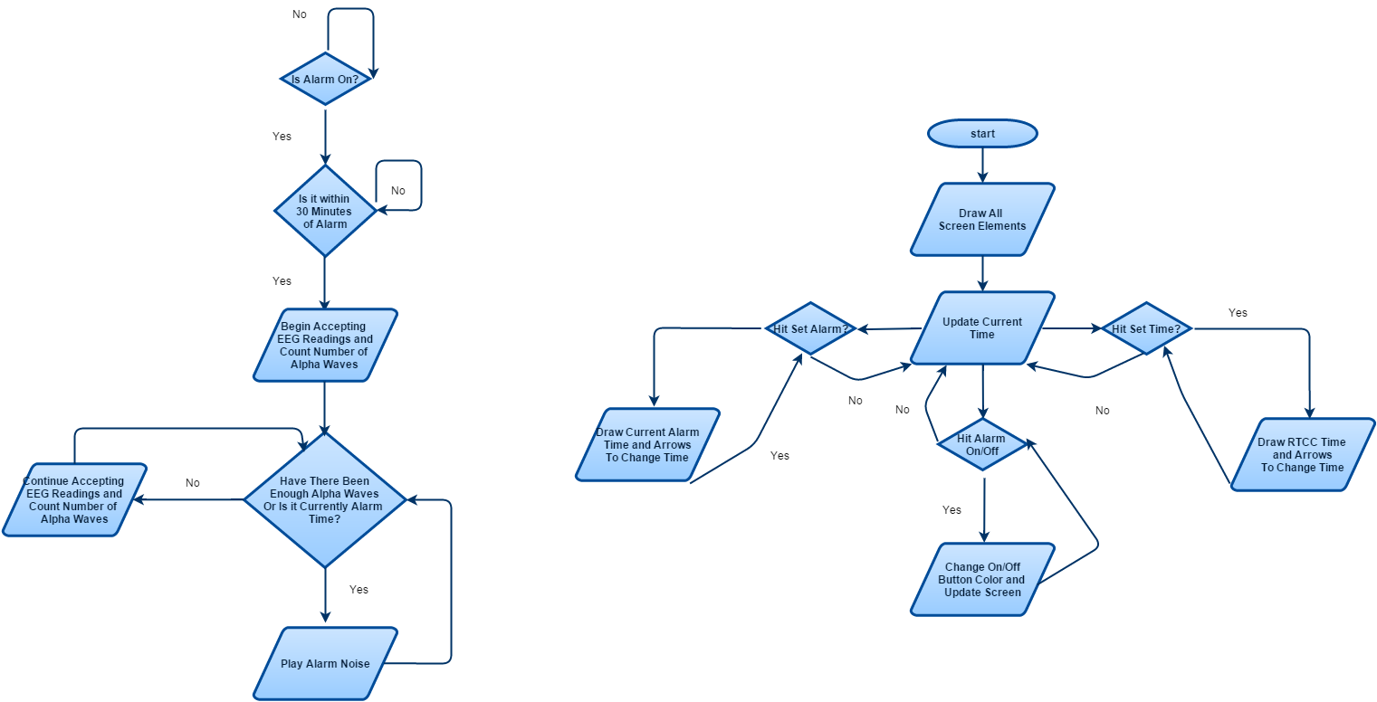
We implemented the sleep cycle analysis in its own thread. Our sleep cycle analysis started processing thirty minutes before an alarm time only if the alarm was on and the user had the headset on. We could determine whether the user was wearing the headset using the signal quality value. The sleep cycle analysis was greatly based off the EEG related sleep cycle research we had done. The goal for this sub-system was to detect a light sleep state. From our research, we determined a distinguishing feature of a light sleep state was a peak in the alpha band activity.
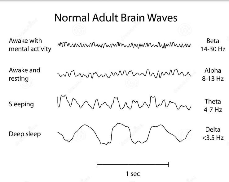
In the image above, you can see that alpha wave typically indicate awake and resting states. Peaks in these frequency intensities may possibly indicate that the brain is beginning to wake up. In software, we kept a count of how many alpha peaks were recorded by the EEG reading sub-system within the thirty minute time frame before the alarm time and then if they reached a certain count, triggered the alarm. An alpha peak was determined by whether the low and high alpha band intensities were above a certain empirically derived number; a value which we believed to be unusually high. The amount of alpha peaks we chose to trigger an alarm was determined through experimentation based off how many we expected to see over a thirty minute time frame when a user was fully awake. We chose 15 peaks to trigger an alarm.
Though this system was rather crudely developed and backed up with limited quantitative data, we reasoned it was a good solution for the scope of the project and the quality of our sensor. If a higher quality detection system was needed, it could be easily implemented within the whole system.
Alarm System
The alarm system is configured the exact same way as the alarm requiring a string of BCD encoded integers. We would give it an encoded string and it would save those variables to its registers. Although the RTC system has its own internal interrupt system, we decided to not use it as it would only ever interrupt when the RTC time and the alarm time were the same. We did not want that functionality so we decided to just check the alarm time versus the current clock time to figure out whether or not the alarm should be going off at any particular time. This worked in conjunction with the sleep cycle analysis as we could just lengthen the period of time in which we would allow the alarm to go off if the EEG reader was also collection the relevant information.
Touch Screen Control
The touch screen gives 3 different values for us to read, an x value, a y value and a z value. The x and y values are the different positions on the screen that you can touch while the z value is the amount of pressure that you are putting on the screen. All in all, with a bit of mathematical shifting involved, we get a values that correspond to different areas of the screen whenever you touch the screen.
One of the most interesting ways that we have written our code was that it only allows you to get one input at the screen at a time because of the latching code. So what we did was that after each time it went through all of the button toggle statements it would call a function that would deal with the one button that you pressed and then reset all of the toggle buttons so that only one thing would change every time you hit a button.
One of the other issues that we had was that the Alarm On/Off button and the associated Alarm would be randomly enabled and disabled. We discovered that the screen would randomly get spikes of incredibly high pressure values on the screen a certain two X and Y values which just so happened to coincide with our Alarm On/Off button area. This was really an easy fix as we just changed the code so that for that button if the Z value was greater than you would ever actually be able to hit on the screen it would not toggle fixing that issue.
LCD Display
The software is organized as really one setup statement that sets the screen up and a then the protothreads continuously loop to check if you have hit any of the appropriate regions on the screen and deal with those appropriately.
Audio Generation
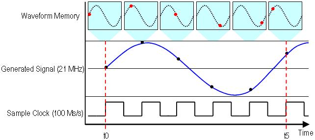
Audio generation in software was done using one interrupt and a couple helper methods. We generated the audio signal using Direct Digital Synthesis. Direct Digital Synthesis entails saving a large amount of amplitude samples of sine wave in a table and iterating through each of the samples so that they can each be sent to the DAC over time to generate an actual audio signal. The sample values were sent to the DAC via SPI communication protocol and we used two helper methods provided by our lab instructor to do this. The iteration and sending of the samples was all done in an ISR. The interrupt for the ISR was thrown by a PIC peripheral clock set to go off at a certain frequency. The rate at which you iterate through the sine table controls the frequency of the tone generated. For our purposes, we only need to generate one frequency, so we iterated through at a constant rate.
In addition, we wanted the alarm to simulate a sort of bleep bleep bleep bleep sound. To do this, we turned the audio generation on and off at a certain rate within the alarm control thread once the alarm was triggered.
Page Directory