Display System

Operation

When originally planning our system design, our display system was an area of contention. We had initially planned to upload our results online through TCPIP server but ultimately we decided to use the AdaFruit Touchscreen LCD we had been using for our labs due to time limit concerns.

Our planned display system included a simple statement letting our user know how many people were currently in the dining hall of their choice. It would also include a visual aid; a listing of each seat at a specific table color coded. Red for unavailable set and Green for one that is available. We decided that this would get the message across simply and effectively.

IMG_20151214_061719

Display, lit with information

Table Monitor

Operation

This second component of our system was tasked with monitoring specific tables and letting the user know exactly how many people were at each one. It employs PIR Motion Sensors we purchased from AdaFruit. The sensors would be placed above each seat at a table and would be able to monitor that particular seat.

IMG_20151214_055626

Single PIR Motion Sensor

Setup and Design

Our initial designs for a table monitoring system called for a variety of sensors including proximity sensors and ones with cameras. All of these were hashed one after another due to pricing or practicality reasons, and we settled on the motion sensors mentioned above. The sensors (pictured below) had spherical field of view because of their shape. They output 0V when detecting motion in this field or a solid 3.3V when detecting no motion.

Much like the lasers before them, the wiring on the sensors were very weak and not very suited to our application. We had to apply similar modifications. In addition, the unnecessary inceased field of view on each sensor proved to be a headache when testing as our sensors kept sensing objects outside of the area directly below them we wanted them to monitor. After some thought, another trip to the school hardware shop followed, where we successfully limited their field of view using some PVC piping. The illustration below shows this.

IMG_20151208_072508

Modified Sensor with PVC piping attached, limiting field of view

IMG_20151208_072630

Front view of modified sensor

Laser Link Body Count

Operation

The Laser Link Body Count system was responsible for monitoring the number of people at any specific point in time at any dining hall employing our system. It uses an ingenious combination of lasers and photoreceptors, two of each, to achieve this, placed one in front of the other. Each laser would be met on the other side by a phototransistor, both placed on one side of monitored dining halls. As people walked into a hall, they would trip the laser, then the other laser. Our microcontroller would record the time at which these two actions occurred and preform some simple algebra to figure out if a person was leaving or not.

F


  • The Laser Link would be placed at least at waist height to make sure people trip the lasers as they walk in and also avoid inaccurate readings from lasers being tripped by two legs from the same person.

Setup and Design

Lasers

The lasers we used were provided by our very own Professor Nadovich instead of the purchases we had already planned. They were the very ones the school used for its audio over laser projects. Setup was achieved through the use of an external 9V battery scaled down to the required value. Though the lasers could have been powered with voltage from our microcontroller, the use of external sources was a design choice we made after consideration of the distance that needed to exist between them and the phototransistors. After getting them setup, we were ready to proceed with the phototransistors.

IMG_20151208_071718

Laser : Front View

IMG_20151214_052037

Laser : Back View, alterations made are visible, including altered wiring.


Through very fortuitous, the lasers we acquired were not without their problems. The default wires were very weak, short, frayed, and much too weak to even penetrate our breadboard let alone hold up the relatively heavy lasers; and as such, made testing a right pain. We had to custom-make stands for them through the school hardware shop, and make sure to add extra wire to increase length and use some heat-shrink tubing to enhance their durability. A visual of the modded lasers as well as the accompanying circuit can be seen below.

IMG_20151214_050534

Laser with Accompanying Circuit

Phototransistors

We were also given some phototransistors to work with by Professor Nadovich. These served as the other half to the system by detecting the lasers and sensing when they were tripped. They ran on power supplies in the range of 1.8V to 5.5V, which could easily be supplied by our microcontroller. When not detecting the phototransistors defaulted to outputting 0V, and output a voltage of 3.3V when detecting the lasers. Setup of the phototransistors included the use of an MCP6242 op-amp comparator for getting more precise outputs for aid in calculations.

After setup was completed, testing was relatively straight-forward. We monitored the photo receptor output voltage from the phototransistors through oscilloscope to make sure expected operation was achieved and verified that it was. The scope-capture below shows our two phototransistors tripped one after another; each outputting a voltage of 3.3V for the duration and returning their default 0V output after.

IMG_20151208_073411

System Hardware Design

The total functionality of the system was planned to be divided among two components that would operate together to achieve total functionality of the system.

The Laser Link Body Count system was responsible for achieving the total body count in the monitored dining hall. The Table Monitoring system would keep track of individual people at each table. Details on each are provided through the links below.

Parts List

Part Price
Lasers (x2) Free
Phototransistor (x2) Free
MCP6242 Op-Amp (x2) Free
Laser Mount (x2) Free
PIR (motion) Sensor (x4) Free
Motion Sensor Housing (x4) 40$
Various resistors Free
PIC32MX250F128B (x1) Provided

Final Status Report

Week 4

This last week of the project saw us take the final steps to finish up the functionality of our project. Our main goals for this week were as follows:

  • Pick up hardware implementation gadgets we had made by the hardware shop including laser mounts and guards for the motion sensors.
  • Implement testing using the gadgets.
  • Setup and finalize the project functionality.

Laser Mounts

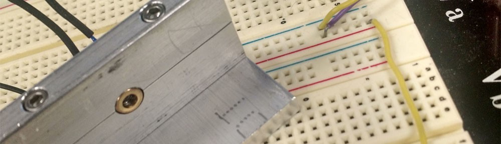
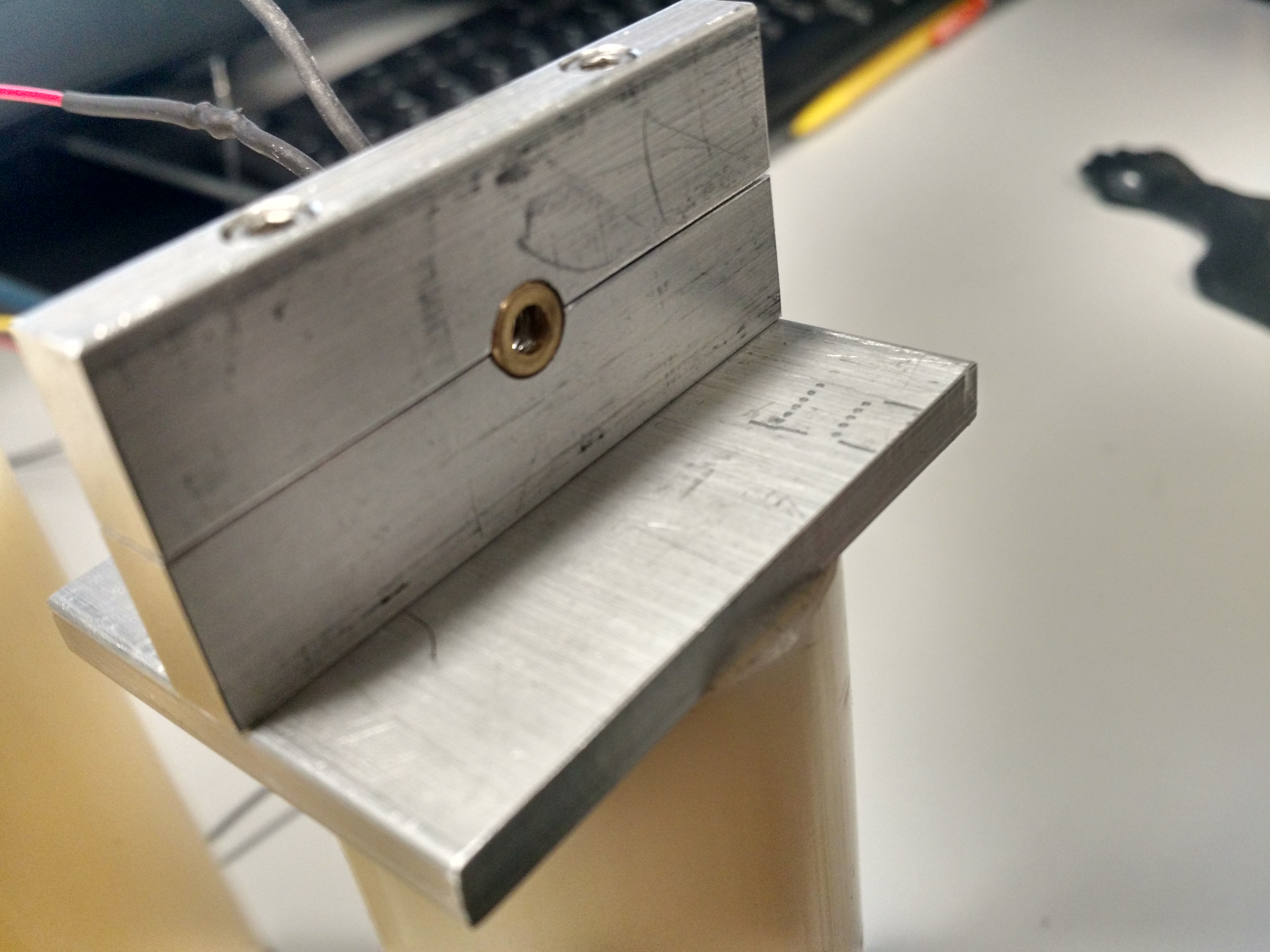
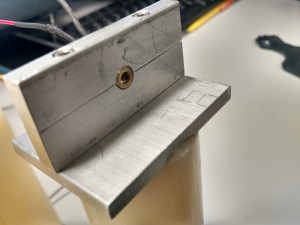
On Thursday, we received our laser mounts from the hardware shop. These were designed and requested by Preston in week 3. The mounts greatly improved our testing procedure as they brought an extra degree of stability that was welcome. The mounts are pictured below.

In addition. Raji resoldered the connections to the lasers for length and a sturdier connection. Heat shrink tubing was also used to cover the joints between the two different wires. This process required a soldering iron, 24 gauge wire and an heat gun.

IMG_20151208_071718

Sensor Limiter

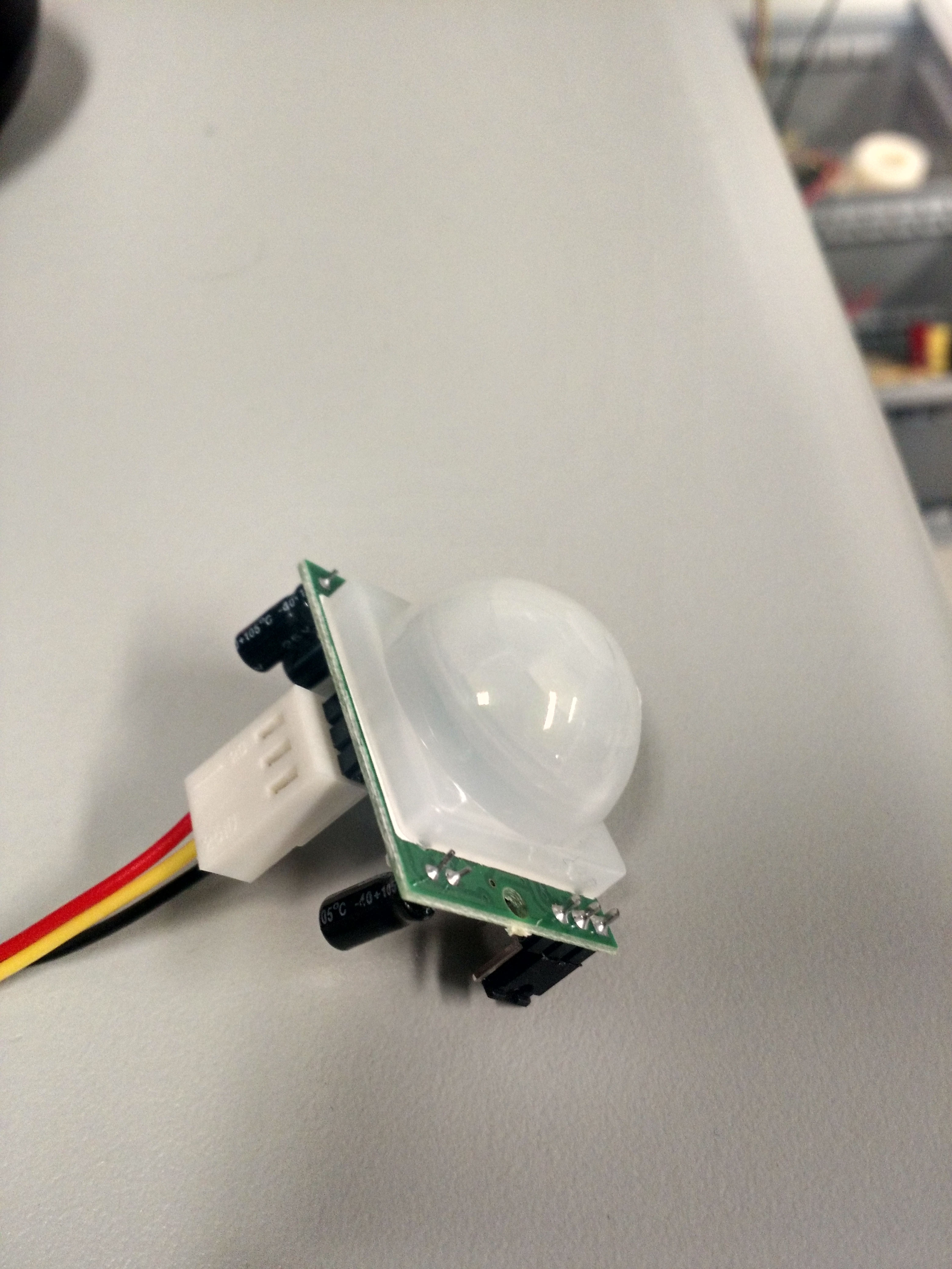
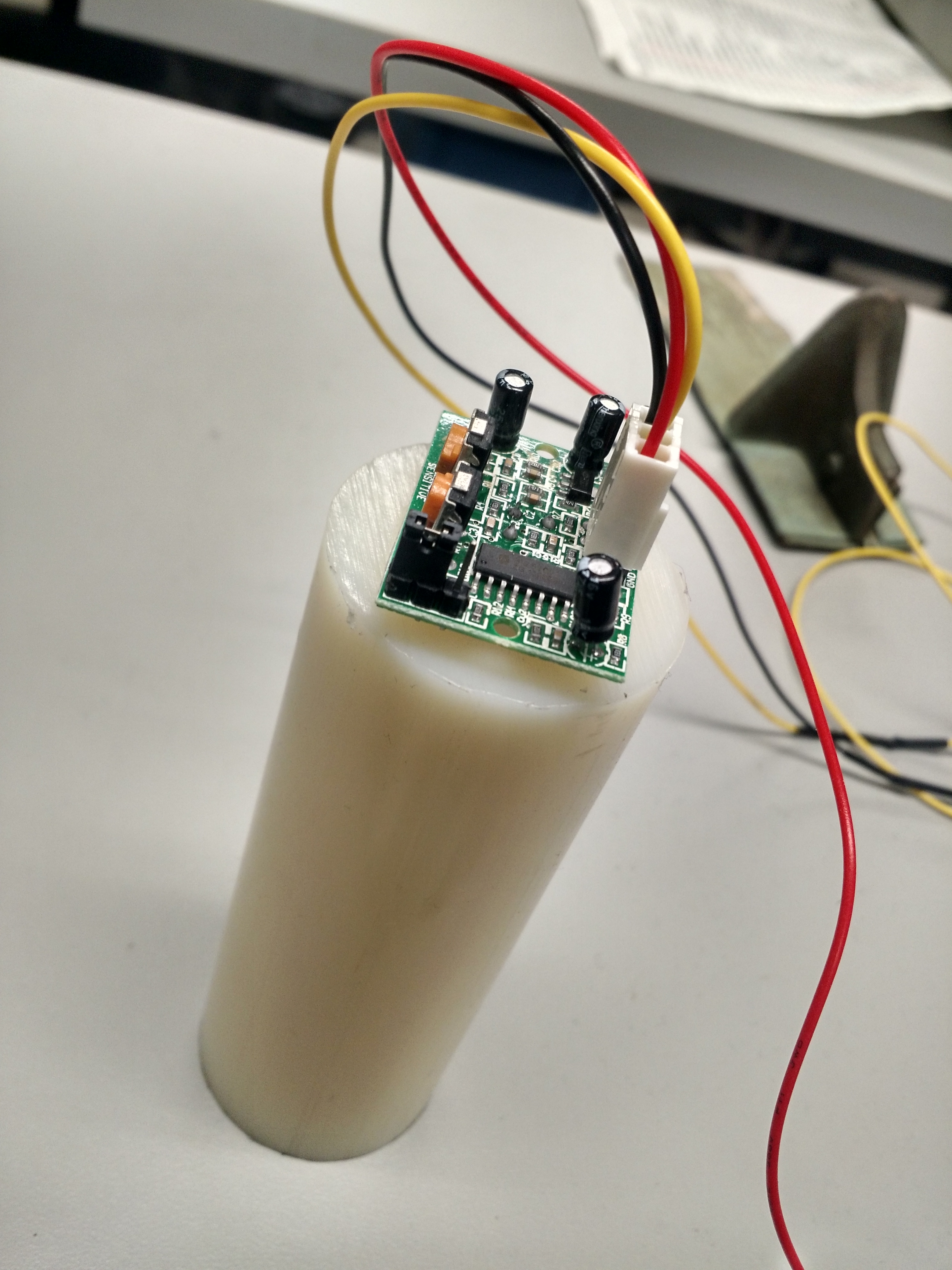
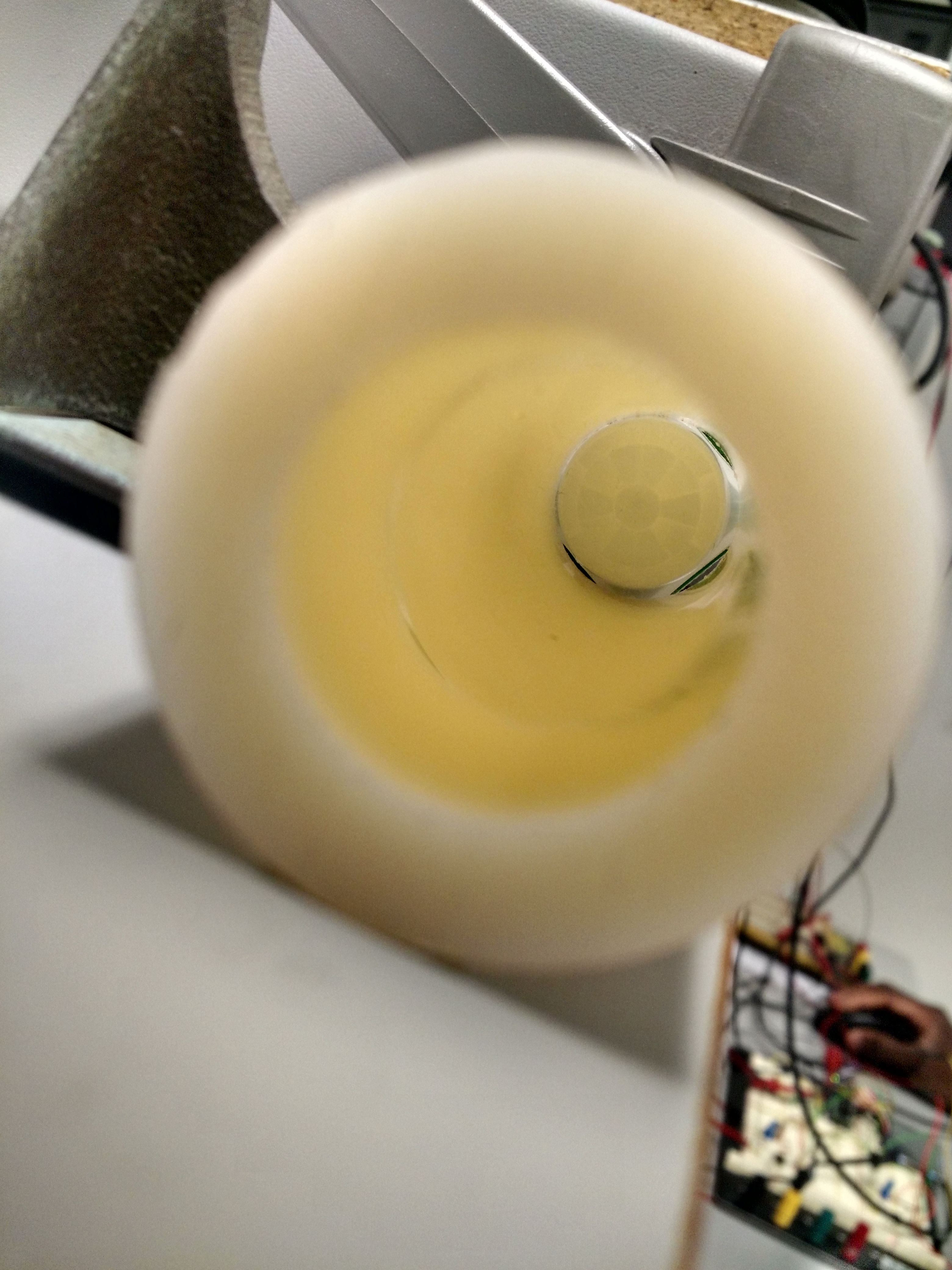
On Friday, we received acrylic tubes we had requested from the hardware shop to limit the sensitivity scope of our Motion Sensors. The sensors initially had a spherical scope that was much too wide for the application we had in mind. Our plans were to suspend motion sensors above each seat at the table to be monitored and the relatively large default scope would keep picking up readings from other seats. To combat this, we used the tubes to limit the scope of the sensors strictly downward. The Sensor + Tube setup in question are presented below.
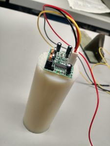
IMG_20151208_072508 IMG_20151208_072630

From Top                                                                       From Front

Mounted Hardware Sensor Testing

Laser Link

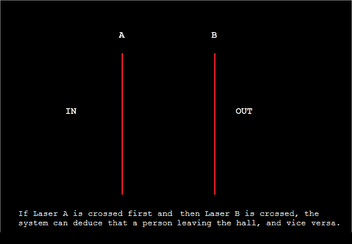
After installing the lasers into our mounts and positioning the phototransistors and the corresponding circuits in place, we ran some hardware tests. Results were as expected. The phototransistors have a low voltage output if detecting the laser and vice versa, by blocking the laser a high output is observed. Scope output results from the phototransistors are shown below are shown below.

IMG_20151208_073411

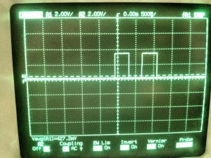
  • The picture shows the output from the Laser link circuit as Preston walked through simulating a person walking through a door. The first pulse is the front laser being broken, and the second pulse corresponds to the second laser.

Motion Sensors

Raji ran similar tests with the adjusted Motion Sensors and we got the expected results. A low signal is output from the sensor when nothing has been detected in the field of view and a high is output for a duration of 10 secs when movement is detected. We are using this property to determining if the seat being monitored is empty or not.
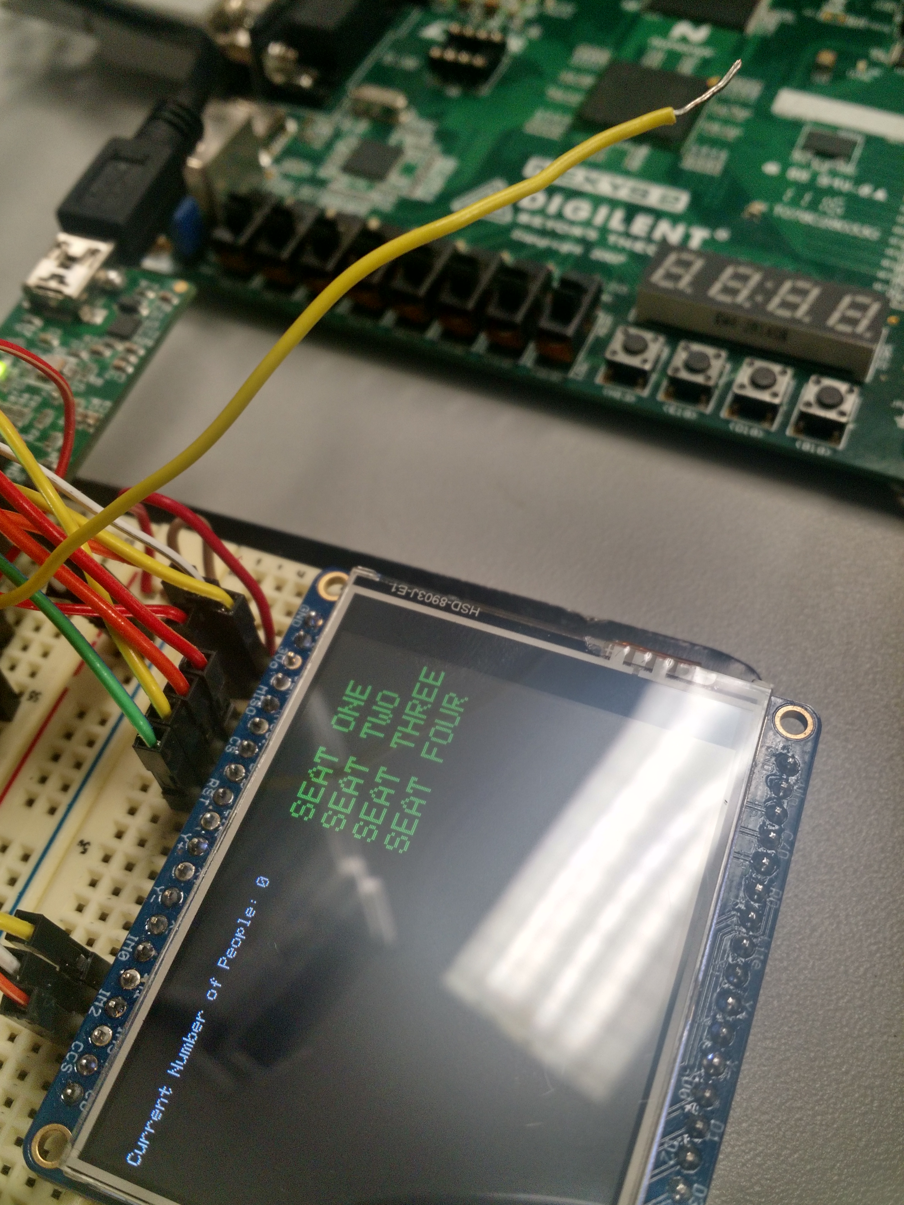
Putting it Together

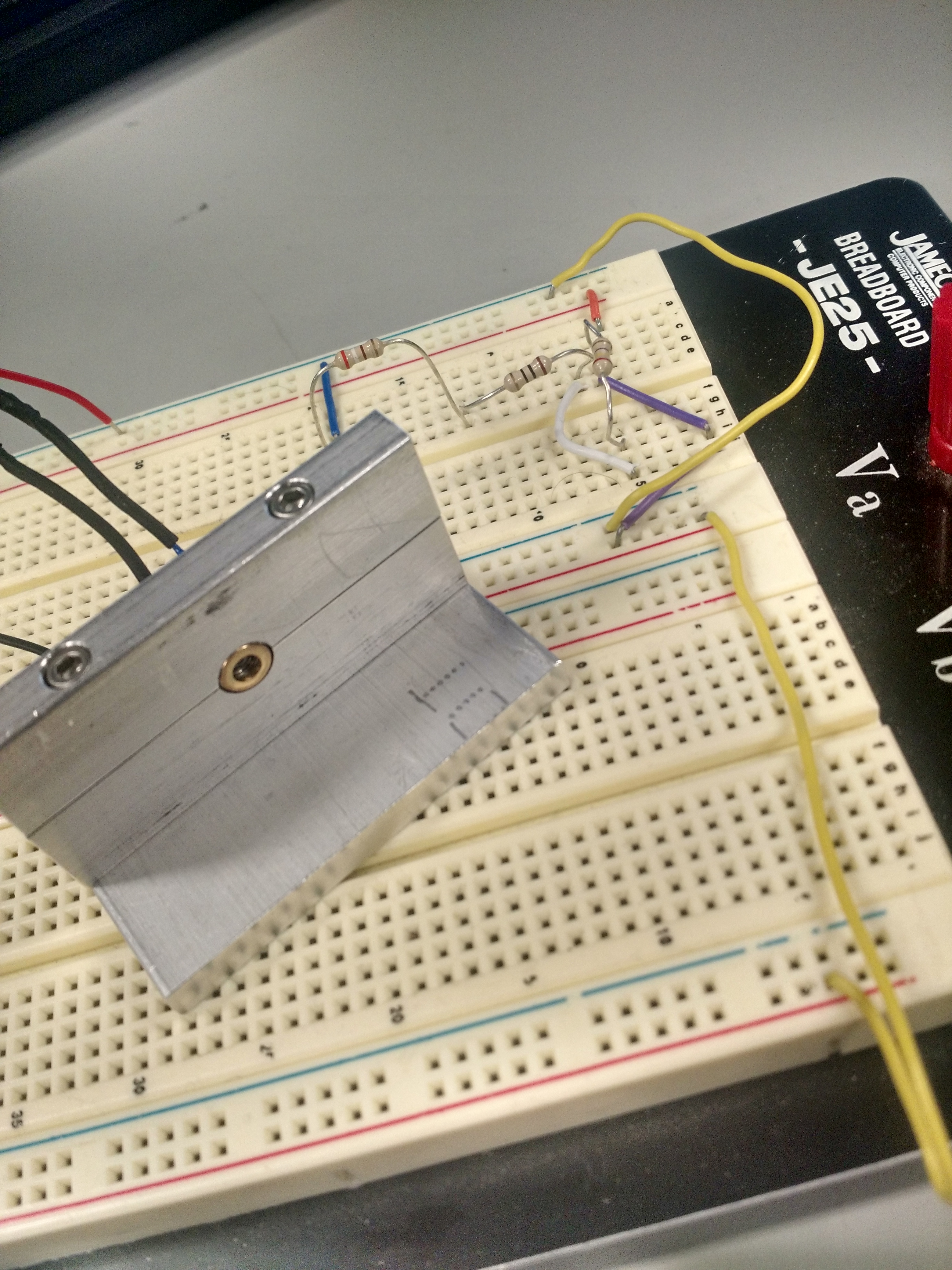
Preston built the voltage regulator/laser and phototransistor circuits of the project. The former being the “transmitter” and the latter the “receiver”. The voltage regulator used a LM317TO-220 which stepped the 9V battery down to ~3.3 for the laser. The phototransistor circuits outputted a high voltage (3.3V) when the laser link was blocked. This is similar to the circuitry implemented in lab 5.

Having gotten successful hardware testing out of the way, for the final part of this week, we focused out efforts on the software side of things. We used the outputs from our laser link to trigger interrupts and figure out if somebody was going or leaving. And we used our motion sensors to monitor table activity. The interrupts have been giving us severe trouble however not triggering when expected.

Week 4 Status Update

This is was our final week of work. Our goals for this week were to implement the EEG reading system, finish the RTC implementation, finish the alarm system including adding audio, and add a dimming feature to the screen. We were able to accomplish most of these goals and consider this week to be a very successful one.

Rich primarily worked on the RTC and alarm control system updates for this week. We were able to calibrate the RTC to a more accurate timing and further update the functionality of the clock, including setting the clock time with touch screen controls. This proved to be much more difficult than expected because of the strange format in which the the clock values are set in software–they are set in hexadecimal BCD format. We were able to do this most effectively by converting the value on the screen to a String value and then converting this string to an integer using base 16. We also encountered a lot of problems using the touch screen controls along the way, but we were able to find solutions to all of them. Rich also worked on implementing the alarm time control features using similar methods. In addition, we implemented the alarm signalling and were able turn on and off the alarm so that an audio signal was sent to the DAC whenever the real time matched the alarm time. The alarm can be turned off using touch screen controls.

Kyle primarily worked on the EEG reading aspect and was actually able to make some progress with it. The main problem he faced was the functionality of the FIFO buffer on the UART receive peripheral. The buffer was filling up and then rejecting values and we could not figure out how to clear the values from the buffer. We were able to find a way to do this and fully read and parse an EEG data packet sent out by the Mindflex headset. These data values can be printed on to the screen and were implemented as a control feature for the alarm. The alarm control checks a certain frequency band for intensity spikes once the real-time clock gets within a certain time range of the alarm-time, and if there are enough, this indicates a light sleep state. If a light sleep state is detected the alarm is triggered, waking the user up in an easy way.

Jae worked on the dimming the feature of the screen this week. He was able to get the feature worked and set 5 individual brightness levels on the screen. He worked on this aspect in parallel to the Real-time clock on a separate board. When we tried to integrate his feature with the main board we were working on, we had some issues getting the desired functionality. The screen will dim, but it will also blink with the high intensity. We are still working on a solution to this problem.

It is also important to mention that throughout this project, all members of this group helped each other with their respective tasks, other than just working on their own decided responsibility. E.G. Rich helped with the EEG headset, Kyle and Jae helped with the clock, and Kyle and Rich helped with the dimming features. Plans for the future include improving touch screen performance, improving clock accuracy, getting the dimming feature working in the fully integrated board and improving the EEG control system to better detect light sleep states.

Final Status Report

During the final week of the project, we finish each out the separate components and combined them to make the final product.

Joe implemented Uart communication between the fingerprint scanner and the PIC. This had been a problem during the past week, but the correct protocol for sending command packets to the fingerprint scanner from the PIC has now been implemented. Using the fingerprint scanner documentation with assistance from a library in C++ for Arduino found on Github, all the necessary fingerprint functionality could then be implemented. The fingerprint scanner is able to perform initiation, enroll, deletion, and fingerprint comparison functions. These were tested by displaying the response from the fingerprint scanner on the LCD display after each command was sent. The response would either return acknowledgement or error messages which could be interpreted using the fingerprint documentation. The fingerprint library was written so that functions could be performed completely after being initiated by one variable in main. The fingerprint scanner was also soldered to a nicer looking proto-board.

As far as sound production, Phil had an issue last week where he was unable to produce appropriate sound from the SD card. The music files were played at lower frequencies than they were supposed, causing the song to play slower than usual and had a large amount of static. Phil was initially using interrupts to send data out to the DAC. This was interrupting the process of reading from the SD and performing DMA transfer. Previously the interrupt triggered a DMA cell transfer and generated a chip select signal for the DAC. This was fixed by moving this functionality outside of the interrupt and little use of the main processor. Chip select was using output compare in dual compare mode. The DMA cell transferred was triggered using a timer. This allowed for a complete transfer of data to the DAC the wav files could be played at normal speeds.

Austin wired the board and did the interfaces. He stripped the board of its spaghetti wires and rewired it beautifully. He made displays for history, enroll, and enrollment list. History included a list ID’s who had rang the doorbell. Enroll includes a song selection screen as well as demo song functionality. He combined code from Phil’s SD card reader to work for the interface, which included creating wrappers and organizing data in a way that it could be used in the rest of the project. The screen and the DAC are on the same SPI channel, so unfortunately it is impossible to use the touch screen while listening to a song. We initially had the screen with the SD card reader, but it caused the SD card reader to stop. Enrollment list displays all the ID’s which are enrolled and the songs which they are mapped to. The ID’s come from the code that Joe worked on.

In the end, we all come together in order incorporate all of the elements into the fingerprint scanning doorbell. This took much effort from all group members to make their separate contributions work together.