Introduction
The Musical Fingerprint Scanning Doorbell is a doorbell which rings with different tones based on who rings it.
The Musical Fingerprint Scanning Doorbell uses a fingerprint scanner which can capture an image of the doorbell ringer’s fingerprint and store it into memory. Fingerprints which are stored into the system can be correlated with a specific tone by the owner of the house. The doorbell tones can be saved on an SD card in the format of a .wav file, and the tones will be displayed on a LCD touchscreen which the user can interface with. The user can enroll visitors and associate their fingerprints with a specific tone. The user can also view a list of enrollments and the song which they are associated with at any time using the LCD display. When the doorbell is rung, it will play the tone which is associated with the fingerprint of the person who has rung it. If the fingerprint is not enrolled in the system, a default tone will be played. The doorbell will also record a history of who rings it which can be viewed on the LCD display.
This project was chosen because it could improve home security. In order to keep one’s home safe, one must have awareness of who is attempting to gain access to the house. By installing these doorbells, household owners would be more aware of who is at the door. Having specific tones for common visitors would give the owner a convenient notification of who is ringing the doorbell before answering the door, and it would keep the owner safe by providing the awareness that the ringer of the doorbell is unidentified. This would be especially useful in a dangerous situation if the ringer has the intent of causing harm to the owner. Overall, this project was chosen because it adds useful features to a common device found in nearly every household.
System Design
Inspiration for this project was drawn from the idea that phones can be set to play different ringtones based on who is calling. This is a common feature that many people use as a convenient notification about who is calling them.
No other system exists which implements all of the functionality in our system. On August 23, 2010, a patent was published for a “Smart Doorbell Security System” which identifies visitors using a fingerprint scanner door bell system (“Patent US20120044049” 1). The patent details a system that records a fingerprint and informs the user who is at the door by having an interface that says their name as opposed to ring a doorbell tone. It does not provide musical feedback based on who has rung the doorbell.
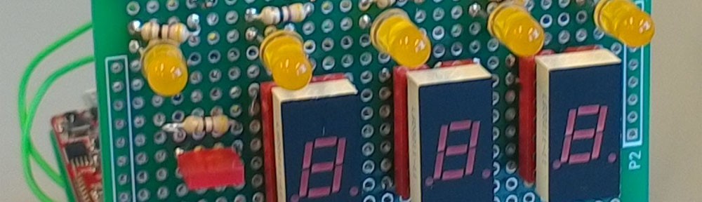
Our implementation of the musical fingerprint scanning doorbell is shown below:
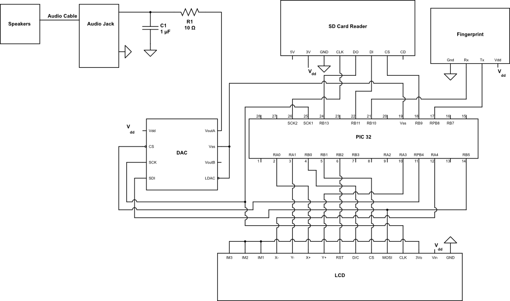
Figure 1: System Schematic
Communication occurred between several exterior peripherals and the PIC32. The SD card reader, DAC, and LCD display each communicated through SPI while the fingerprint scanner used UART serial protocol. A low pass filter was also included to smooth out the analog signal going to the speaker.
Fingerprint Scanner (Fingerprint)
The fingerprint scanner code handled both communication with the fingerprint scanner as well as functions to perform higher level operations such as enroll fingerprint and initiate a doorbell ring. The datasheet of the fingerprint scanner included a list of functions which could be performed in response to a UART serial signal, so a library of fingerprint commands was implemented using the given functionality in the datasheet. An example library on Github for Arduino in C++ by Josh Hawley was also used a reference as it contained higher level processes such as enroll as well as a library of commands with more detail descriptions than in the fingerprint scanner documentation.
In order for the fingerprint scanner to perform a certain function, it must receive a 12 byte signal via UART connection. Software was implemented so that the command packets were sent one byte at a time until all of the bytes were transmitted from the PIC to the fingerprint scanner. The fingerprint scanner would then send 12 consecutive response bytes. Since the baud rate of the fingerprint scanner was 9600, the PIC was able to receive the bytes one at a time from the fingerprint scanner and store them to memory without the need of any UART buffer. Oscilloscope images of UART communication between the fingerprint scanner and the PIC are shown below.
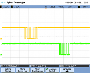
Figure 2: UART transmission for a single command. The top signal is the PIC’s transmit line and the bottom signal is the PIC’s receiving line.
The data being transmitted to the fingerprint scanner is transmitted using little Endian format, and the format of the command packet is described on the fingerprint scanner datasheet as the following: (command start code 1, command start code 2, device ID byte 1, device ID byte 2, Parameter byte 1, Parameter byte 2, Parameter byte 3, Parameter byte 4, command byte 1, command byte 2, checksum byte 1, checksum byte 2). Command start bytes were 0x55AA, while the Device ID was fixed at 0x0001. Command byte one was a value specified by the documentation correlating to a specific command, and command byte two was fixed at 0x00. Code to produce checksum bytes was taken from the Github example library. The response packet would then return in the same format as the command packet, except the parameters would be either output parameters or an error code, and command byte one would be replaced with an acknowledge (0x30) or non-acknowledgement byte (0x31).
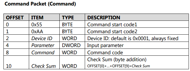
Figure 3: Command Format. Source: Fingerprint Scanner Datasheet
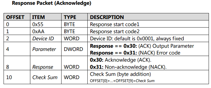
Figure 4: Response Packet Format. Source: Fingerprint Scanner Datasheet
A library was written for each of the necessary functions and includes the following commands: Open, Close,SetLED, GetEnrollCount, CheckEnrolled at index, Enrolling functions, CaptureFinger, Delete one or all ID’s, and Identify fingerprint. Each of these methods would send the necessary bytes to the fingerprint scanner and then interpret the response packet. The Open method must be transmitted before any other actions could be performed, and the LED must be turned on before reading a fingerprint. These methods were called consecutively to perform higher level functions.
As mentioned above, the sequence of commands for enrollment and ringing were found on the Github example code. The doorbell has two modes: ringing and enrolling. The doorbell is always in ringing mode except when the user indicates that he would like to make an enrollment. These modes are determined by a user input variable which is set in the top level. Ringing the doorbell involves turning on the LED and checking to see if a finger is pressed. If a finger presses the doorbell, the fingerprint scanner captures the fingerprint image and identifies if this fingerprint matches a fingerprint on the scanner’s internal memory. The fingerprint scanner sends a response packet indicating if the fingerprint enrolled in the system and returns which ID it is saved at in the first output parameter of the response packet.
Enrolling an ID was initiated using the state machine below:
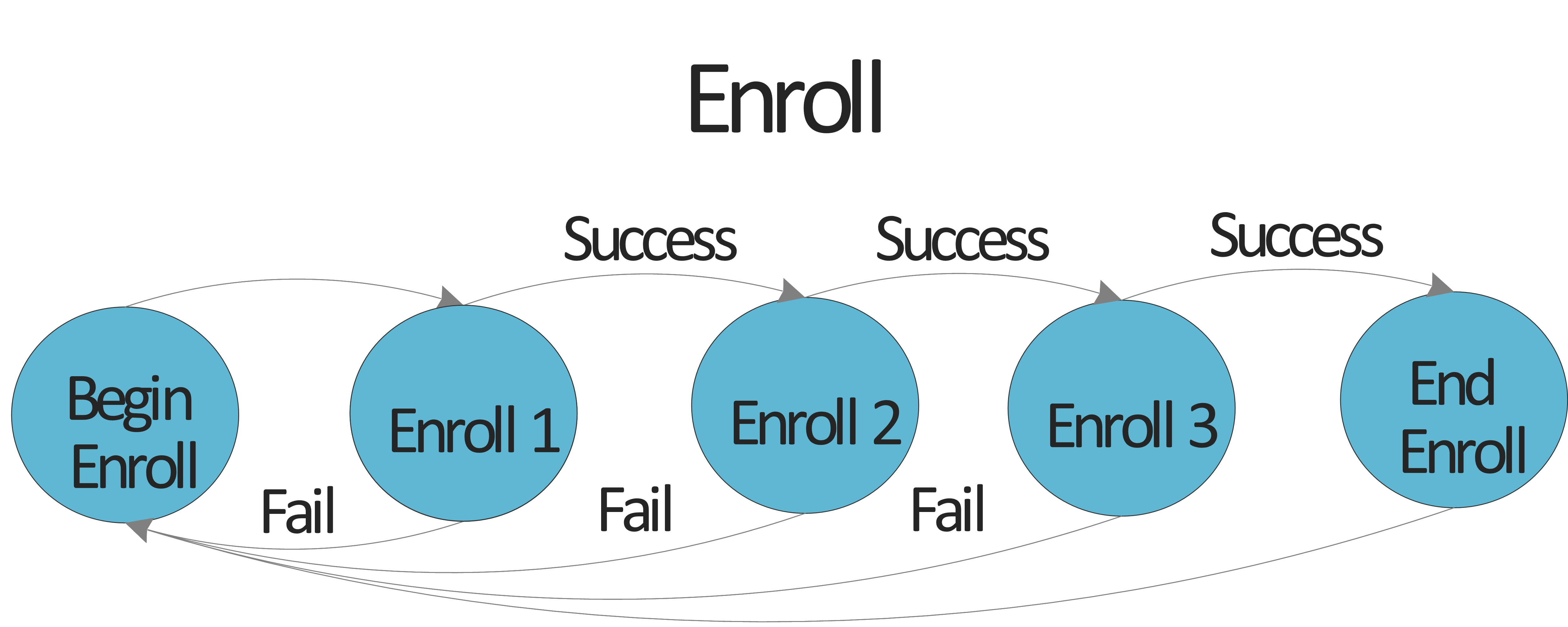
Figure 5: Enrollment State Machine
When the User input indicates that an enrollment is to occur, the fingerprint scanner will commence Begin Enroll. In Begin Enroll, the fingerprint scanner finds the next available index to store a fingerprint, ensures the LED on, and calls EnrollStart. After begin enroll, the fingerprint scanner requires three separate images of a fingerprint in order to enroll it. These images are taken in each of the enroll states 1, 2, and 3. Each enroll waits for a finger to be pressed, captures the finger, and then enrolls the finger. If this is successful three times, the fingerprint scanner will reach the end enroll state and the doorbell is set back into ring state. If any of the enrollments fail due to error in capturing fingerprint, the process restarts from the begin enroll state.
Delete all IDs is called when first running the code to ensure past fingerprints are erased, and a function is available in the fingerprint library to delete a single specified fingerprint, but this function was not implemented in our system.
As for fingerprint scanner hardware, the fingerprint scanner has four pins. Two of these pins are used for UART transmit and receive signals while the other two pins are for high and low voltage. This peripheral could be used with any device which communicates through UART serial protocol as long as 3.3V-5V can be provide to power it.
The most difficult part of the fingerprint scanner code was to set up UART communication. It took time both to understand the command packet formatting as well as how to set up UART on the PIC to transmit and receive. Once this was worked out, the LED screen was used to display the response packet from the fingerprint scanner. This was extremely helpful in coding the enrollment functionality of the fingerprint scanner. The response packet would provide an error message indicating what was wrong with the system when attempting to enroll a fingerprint, and this made it significantly easier to diagnose problems with the code. The other tricky part was reacting to a fingerprint error when it occurred. This was handled by setting specific flags if there was an error. This was most important in enrolling a fingerprint because the enrollment process had to be restarted if there was an error in capturing a fingerprint image.
SD (contained in SD.c)
In order to play music from audio files, external memory had to be used. The audio file type used in the design generally takes up 10MB of space per every one minute of song data, but the PIC32 only has 128KB of on board memory and therefore will not be satisfactory to store song files. An SD card was used as the external memory because of its ability to adhere to SPI protocol. Code was found online that interfaced with an SD card, but was for Arduino and a different type of SD card (SD code source). This code was still used and modified because it was a fairly simple library. One of the most challenging issues to overcome was the modification of the code to work with the PIC’s SPI buffer setup. There was no direct conversion of the simple SPI write and read operation given in the code. In the PIC, an RxBuffer flag is frequently set to signal an overflow and prevents any more data from entering the buffer, which is problematic for a multi-byte read operation. For our SD card (SanDisk 8GB SDHC), a different SD startup protocol was needed and it roughly followed pages 8-9 of the SDv2.0 documentation (SD association documentation). Additionally, the SDHC card was sector addressable instead of byte addressable like the one used in the example code. This picture illustrates the PIC requesting a sector of data and the SD card’s initial response followed by a data packet (see Figure 6).
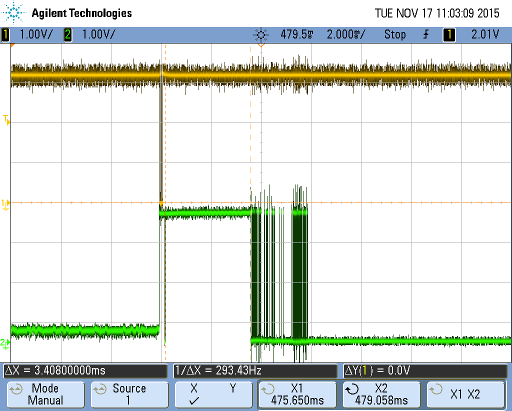
Figure 6: Example of a sector read. The master (yellow) sends out a cmd signal specifying a sector address. The SD card (green) acknowledges quickly and then a few ms later sends out the requested sector.
FAT (contained in fat.c and fat.h)
The data contained within the SD card is formatted as FAT32 and navigating the file system is necessary if one wants to access relevant data. All of the relevant files were stored in a music directory. From there, starting sectors and clusters were found and accessed. A sector is 512 byte chunk of data that can be directly requested by the master device (PIC). A cluster is a collection of sectors that are guaranteed to store data for only one file. To get to the next cluster associated with a certain file, the FAT table must be consulted. The FAT table is an allocated section of data on the SD card that holds an array of pointers to each cluster. Once the beginning part of a file was found, traversal required reading consecutive sectors and once the end of the current cluster is reached (every 64 sectors on our card), finding where the next cluster of data is by checking the FAT table. The same author who wrote the SD card code modified in the last section also had fairly simple code for navigating the FAT16 file system (FAT16 code source). His code was almost entirely gutted to upgrade to the FAT32 file system and functions were added that allowed for music playing, which will be discussed in the next section.
Music (contained in sound.c)
WAVE (.wav) files were used as the source of the audio in the design. When doing preliminary research for the project, an example of someone playing WAVE music off of a microcontroller was found (video), so it was known to be possible (no other parts of that design or code were used though). WAVE files are optimal on a microcontroller because they are uncompressed and require little computation to format the data into an audio signal. The only downside is the additional memory space, but this was not an issue because our design was not memory constrained. Every SD read resulted in a new sector of 512 bytes being sent to the PIC’s on board memory; however, the majority of this data was dropped due to the design of the system. The WAVE files used in the device all had 2 bytes/sample and two channels. In the layout of the data chunk, data for these channels alternated. A stereo capable device was deemed too challenging, which resulted in the drop of every other 2 bytes to eliminate one of the channels. Additionally, a 12 bit DAC was used requiring the least significant 4 bits to be dropped from the original 16 bit sample. Control bits for the DAC also need to be added to create a 16 bit packet. After all of aforementioned formatting, only 512/2 * ¾ = 192 bytes out of a 512 byte sector were used in 128 DAC transfers.
The data chunk of a WAVE file contains two’s complement integers (WAVE file format). Output values were calculated by adding the modified 12 bit data chunk to 2047, the midpoint of the 12 bit DAC and therefore the midpoint on the speaker.
The WAVE files used all had sample rates of 44100Hz, which corresponds to the rate at which the DAC is latched and outputs a new analog sample. This sample rate was fairly slow considering the SD card can operate at 10-20MHz. The obvious setup here would be to read in a sector of data from the SD card really fast before each set of DAC transfers. However, this method will not work because of the slow SD card response time. The response time was found to be around 1-2ms, which is huge considering a sector of an SD card only lasts 1/44100Hz * 128 transfers = 2.9ms. It follows that these operations would need to be done in parallel and this can only be done using DMA on a single processor device like the PIC32.
Each DMA block will transfer data read in on a previous cycle. In the meantime, data will be read from the SD card and formatted to prepare for the next DMA block transfer. Two buffers were required for this scheme. One buffer received new data, while the other buffer was used as a source for the DMA transfer. After every block transfer and read, the roles of these buffers would switch (the one that got the data in the last cycle will be used as the source of audio to the DAC in the next block transfer) (see Figure 7).
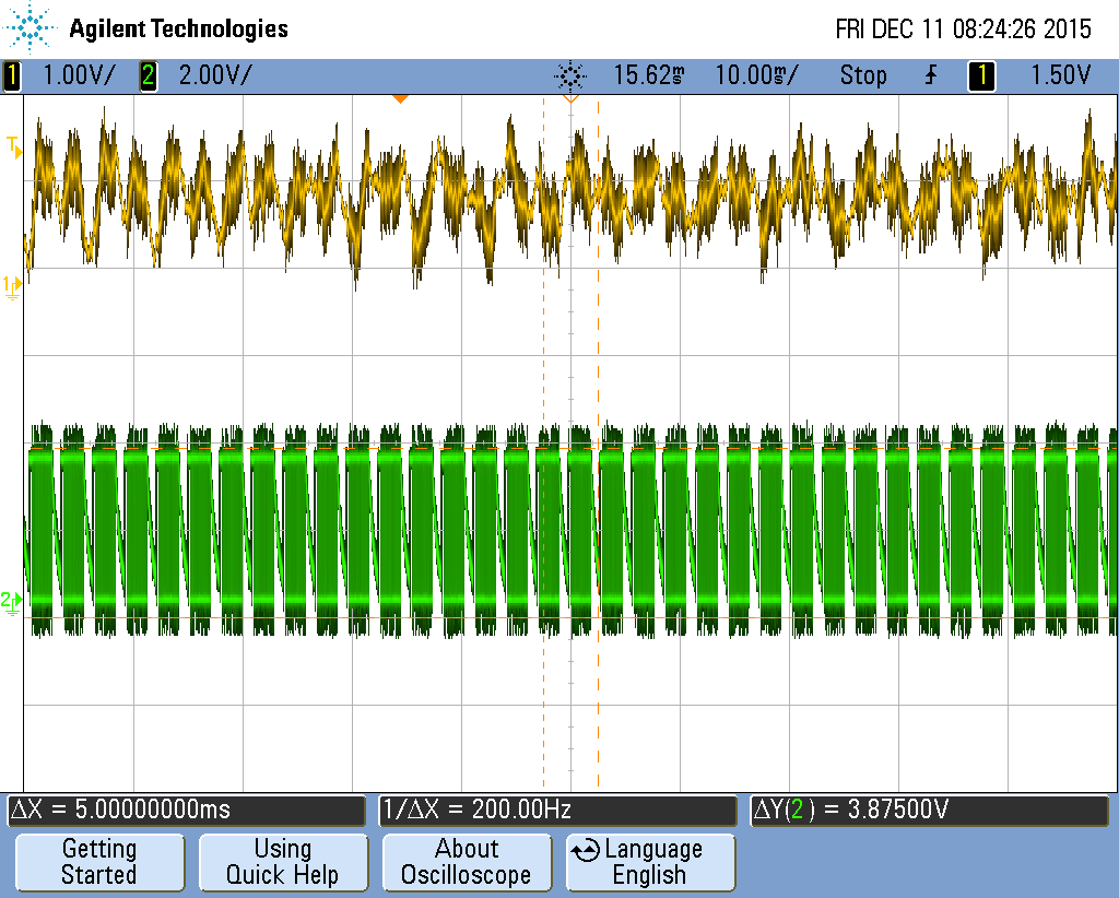
Figure 7: Output audio (yellow) and input data packets (green) shown. Note that music audio is supposed to look this noisy.
Creating a scheme that successfully integrated DMA was challenging and required multiple iterations before the sound production was acceptable. DMA was setup to perform 2 byte transfers to the DAC at each sample interval (a cell transfer). Initially, the cell transfer was started in an interrupt block so it could be synced with a chip select toggle to latch the previous data into the DAC. This method was deemed problematic because it appeared to throw off communication between the PIC and the SD card by taking up processor time (see Figure 8). This functionality was then achieved without the need of any processor time or at most, only a few cycles. Chip select toggling was done using output compare in dual compare mode. Each pulse occurred after 16 bits had been received by the DAC. Timing considerations were found online for this type of operation. It is also worth noting that the DAC will not accept any new data after the first 16 bits as long as CS is not asserted. This allows the data to be sent really fast and does not require precise CS timing (noticed when looking at code using a similar DMA to DAC scheme here). DMA cell transfers were done using a timer trigger feature that occurs outside of an interrupt service routine (see Figure 9).
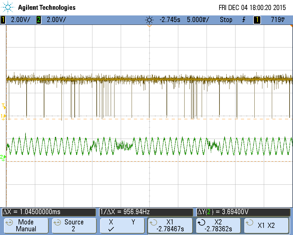
Figure 8: Erratic signals coming from the PIC to the SD card (yellow). Next DMA transfer results in corrupted signal (green).
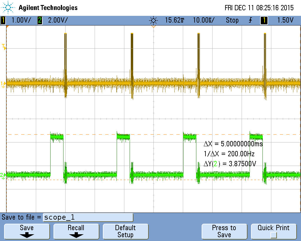
Figure 9: Quick transfer of 16 bits to the DAC (yellow). Chip select pulse using output compare between each DAC transfer (green).
Another issue that had to be solved was the access to the FAT table during the music playing process. Originally, after the last data sector in a cluster had been read, the relevant FAT table sector was also read from the SD card to find the location of the next cluster of sectors. Two reads were not able to fit into a single DMA block transfer and the system faltered (see Figure 10). The solution implemented was to read in the relevant FAT table sectors into a local array before each song played. This did not take up much data (~1024 bytes) and allowed quick look up during music playing.
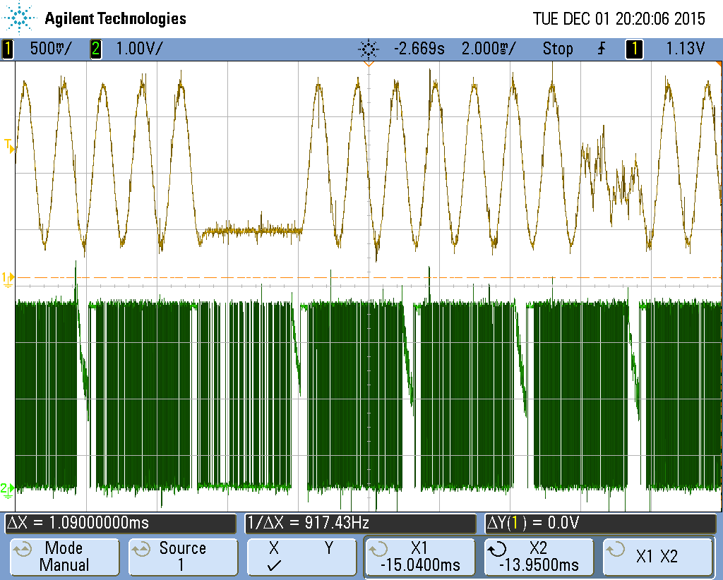
Figure 10: FAT reading during music production throws off output audio (yellow). Around the flat audio signal there are two data packets read consecutively (green). The sparser one is the FAT table.
Interface (contained in main.c)
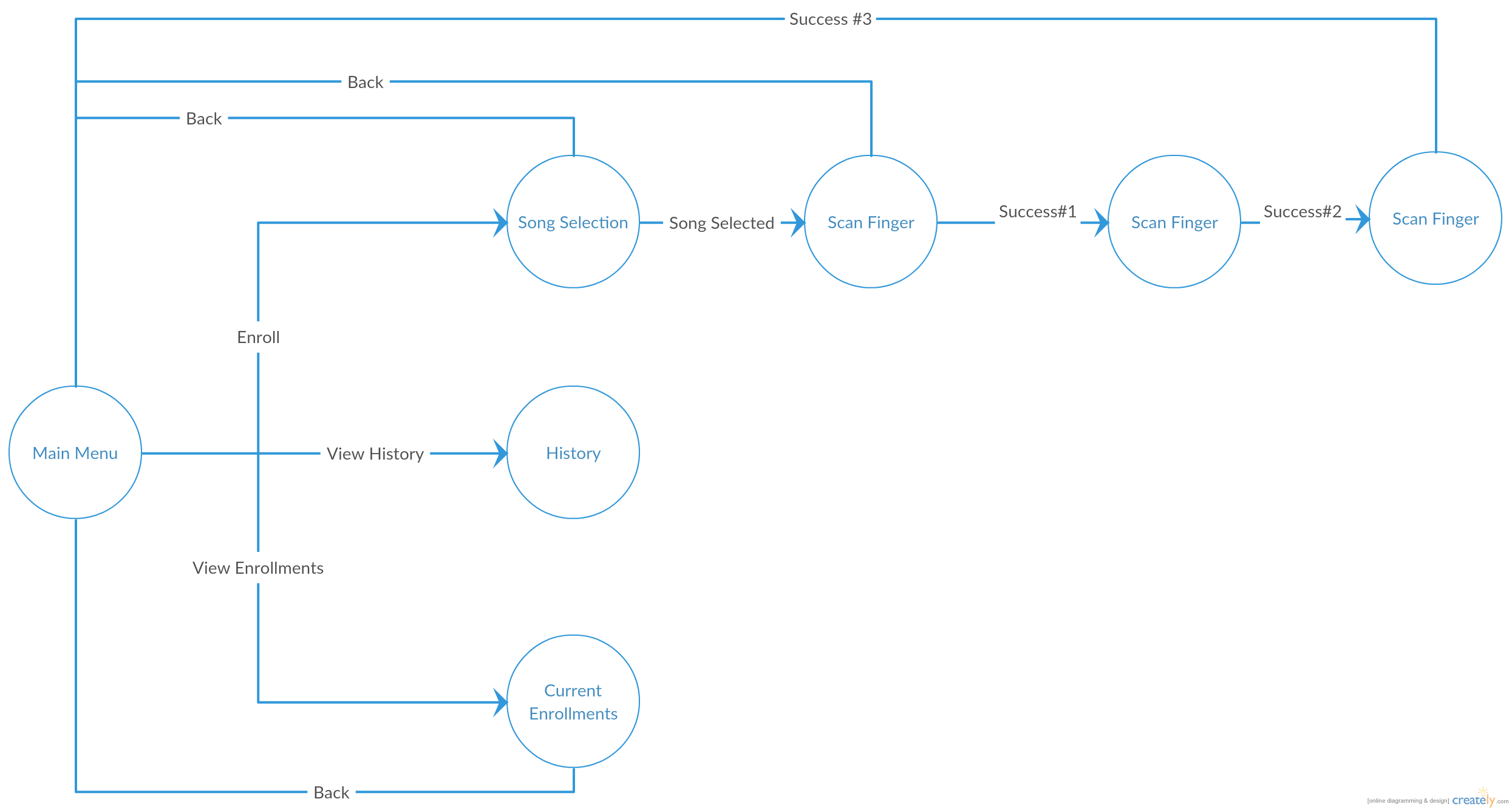
Figure 11: Interface Diagram
The interface consists of a Main Menu with three sub-menus. From the main page, one can view the history of doorbell rings, see all current enrollments and their selected song, and enroll themselves in the system.
When enrolling, the user is first given a choice of songs. These songs are loaded from the SD card upon every startup. The array of songs extracted from the SD card are not all valid. These are partially filtered and the valid songs are added to one of the song select pages. This means that all the user has to do to add a new song to the system is add the song to the SD card. The system only allows a total of 10 songs per screen, but there are multiple song select screens. When you select a song, it will become highlighted so that the user can verify that it is the song they chose. Once the user chooses a song they think that they may like, they can either demo that song or jump straight into scanning their finger.
On the History Menu, the user can view all the most recent doorbell rings. The most recent entries are at the top of the screen, and every entry before that is shifted down the page. If the person is identified, the finger ID and their song of choice is displayed. If the person is unidentified, the entry will only display ‘Unknown’. We initially wanted to implement a real time clock (RTC) in order to display the time that each person rang the doorbell, but we realized that this added an undesired level of complexity and that we would not have been able to implement it correctly in the time allotted.
On the Enrollment Menu, there is only a list of all current enrollments. It will display the enrollee’s finger ID and their song of choice.
Every button on the display is interactive and has accurate touch detection. To ease the flow of the interface, each button has a few key properties: the button title, the color of the button, and most importantly, the button’s action (called next_state). The action property can take the interface to a different page or highlight the button and play a song. When a button is pressed, we detect an overlap of pixels and set the next state of the program as the action of the button. This made it easy to change what a button does. We had to calibrate our touch detection to convert the x-position and y-position of touch to a corresponding pixel on the screen. We did this by shifting the bits of the touch positions down to a range of 0-320 pixels for x, and 0-240 pixels for y. We compare this value to the values of the buttons onscreen to detect overlap.
Results
Sound production was the biggest unknown going into the project, but the sound quality ended up being solid. The frequency accuracy was spot on at least when measuring a simple 1kHz sine wave (see Figure 11). However, two features not included in the sound system were full sample resolution and stereo sound. Most of the audio files used were intended to be played on two channels and the sound data was split between the two. It was clear that some of the audio was missing or was underrepresented during mono playback. Sample resolution, on the other hand, did not seem to have much of an effect on audio quality although one would expect it to considering the output sample was only 75% of the original sample. The lack of effect from the comprised quality may come from the low quality speakers that were used. These were probably not able to produce sound precisely enough for the last bits to matter.
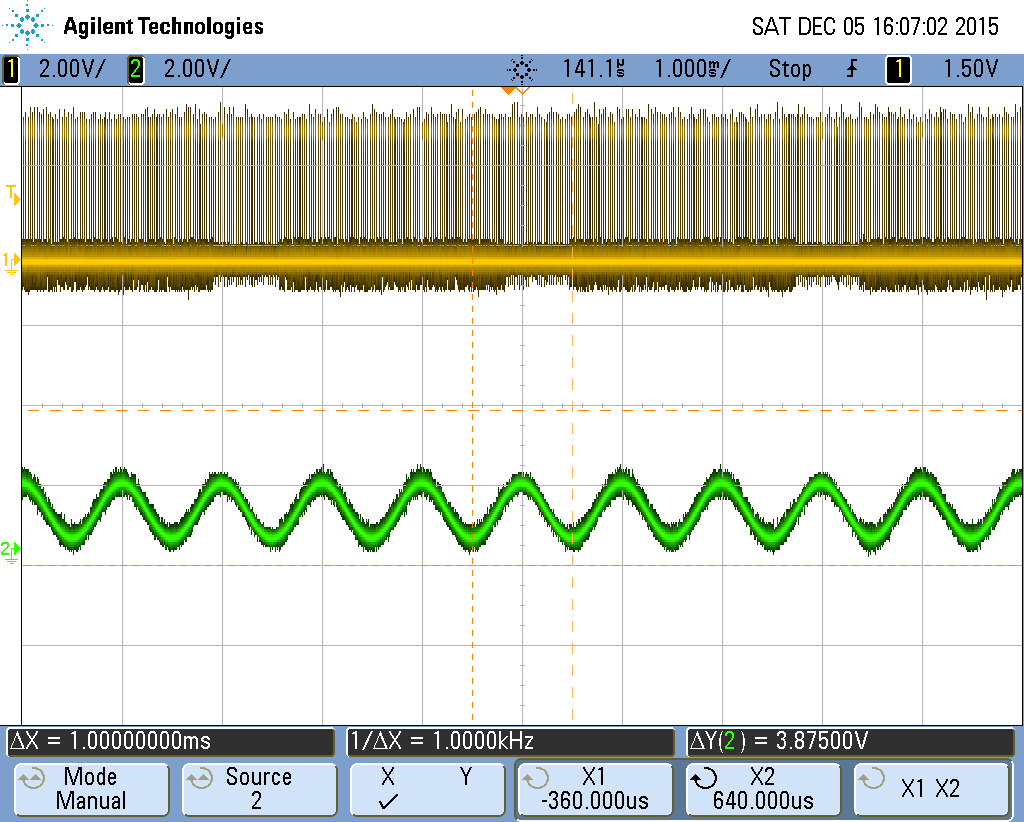
Figure 12: Measurement of an alleged 1kHz sine wave from an audio file (green). Cursor measurement suggests the wave output by the system is exactly 1kHz.
SD interfacing and FAT32 navigation was functional enough to create a prototype, but would not be acceptable to an end user/consumer. The startup sequence used to setup the SD card and get FAT parameters were exclusive to the SD card used (8GB SanDisk SDHC). Different SD cards, such as ones on the FAT16 file system instead the FAT32 file system, will not have their boot sectors or FAT tables read correctly. Also, there was no detection of WAV files vs. other audio file types as well as no specific audio parameter detection. It was assumed that all of the files in the music directory were WAV and had a specific playback format. Also, when importing the files from the SD card there were some bogus files displayed, such as deleted pointers. Finally, FAT only allowed for 8 character file names, which may annoy consumers. There is a way to extend the name, but the basic implementation was used instead.
The fingerprint scanner was extremely accurate and responsive to a press. Songs would begin to play almost immediately upon a touch by any person who was known or unknown to the system. Setting the fingerprint to a fast recognition mode helped with this as well as having the fingerprint enrollment performed at a high resolution setting. One drawback of the fingerprint scanner was the inability to enroll a new person upon a single touch. The scanner required three consecutive touches before a user was entered, which is a huge inconvenience for users. However, there is not much that could be done about his because this functionality was contained with the fingerprint scanner’s hardware and software. Another issue with the fingerprint scanner was that enrolling the same fingerprint twice would result in the failure of the fingerprint scanner and it only produced error messages until it was restarted.
Task management was another area where the system could have been improved. If music is playing or a new fingerprint is being enrolled in our system, the screen will lock and will not be updatable. Better thread and SPI channel management could have made a more flexible system. Importantly, the screen and the fingerprint scanner were able to run in parallel, so a person could ring the doorbell or update settings freely.
The LCD touchscreen was configured nicely. There was no flickering at all because screen updates only occurred upon a touch by the user. The touch screen was responsive and was only registered on a unique touch. In other words, the user’s finger must be removed from the screen before they can interact with the screen again.
Conclusion
Results vs Expectations
We accomplished our goal in designing a musical fingerprint scanning doorbell. There were roadblocks on the way, but overall we succeeded in realizing our vision. We achieved a device that could enroll fingerprints, associate fingerprints with a selected song, and successfully play that song from an SD card when the doorbell was rung by the enrollee. The complexity of our design was high, and it was definitely the right decision to not implement the external server for a criminal database. If there was more time, we would have liked to implement the criminal database component of the doorbell to give it more of a focus on household security.
Standards
SPI
We used SPI protocol to communicate with the touch screen, DAC, and microSD card reader. The TFT touch screen and DAC were on the same SPI channel, and the microSD card reader was on its own channel.
UART
UART serial protocal was used to send and receive data from the fingerprint scanner. Each transmission involved 12 bytes of data being sent followed by twelve bytes of data being received. The baud rate of the fingerprint scanner was 9600.
Intellectual Property Considerations
Fingerprint scanner: An example library on Github for Arduino in C++ by Josh Hawley was used. It contained higher level processes such as enroll as well as a library of commands with more detail descriptions than in the fingerprint scanner documentation.
SD card: Code (written for Arduino) that interfaced with the SD card (SD code source). Code was modified so that we could use it with the PIC32 microcontroller.
Currently, no system exists (other than ours) which implements all the functionality of our system. A patent was published on August 23, 2010 for a “Smart Doorbell Security System” which identifies visitors using a fingerprint scanner door bell system (“Patent US20120044049” 1). This patent does not provide musical feedback based on the ID of the fingerprint, so there are patent opportunities available for our system.
List of Parts
| Component | Price | Vendor |
| Fingerprint Scanner TTL GT511C3 – 3.3V to 6V | $50 | Sparkfun |
| Adafruit TFT LCD screen with touch capability | $28 | In house |
| MicroSD Card Breakout Board+ | $16 | Adafruit |
| 8GB microSD card | $8 | SanDisk |
| Speakers | $8 | In house |
| 12bit DAC (MCP4822) | $3 | In house |
| Breadboard audio jack | $1 | In house |
| PIC32MX250F128B | $4 | In house |
Task allocation
Joe Sluke – Interfaced with the fingerprint scanner and integrated it into the complete system.
Phil Bedoukian – Interfaced with external memory and audio production.
Austin Wiles – Created menu and touch interface. Worked with other team members to integrate their respective parts into the complete system.
References:
Fingerprint Scanner resources Fingerprint documentation Example Code
FAT resources
FAT code example
FAT32 layout
FAT32 explanation
SD resources
SD code example 1
SD code example 2
SD 2.0 documentation
SD card interfacing
SD card lecture
Audio resources
DMA and CS example
WAVE file format
MCP4822 (12bit DAC) datasheet
WAVE file resource
Phil’s Reflection
This project was a lot of work and a lot of fun, and hopefully I have gained a fair amount wisdom into the realm of digital systems. I want to say that I am now a master of memory systems and audio playback, but that is definitely not the case. Clearly, there is much more depth in these fields. Even for the system built in this project, the implementation of the memory and audio systems could have been much better.
I think that the area that I gained the most experience in was debugging. The SD card was one of most troublesome components that I have every dealt with. There were at least three major issues with involving the SD card, all of which took days to resolve. The issues include the inability of the PIC to read multiple bytes off of the SPI channel, the SD card shutting off after about 20ms of lack of use, finding the correct command sequence to startup for the specific card I had, and the finally dealing with period of time where the SD card stopped responding to code that it had responded to before (i.e. without a reprogram of the PIC the SD card went from working to not working).
On these occasions, I had to figure out ways to isolate the problem and reach a state where there were almost no degrees of freedom, which is sometimes a difficult feat when the level of abstraction is so high. The oscilloscope was extremely useful in isolating and debugging problems on the SD card and the card’s communication with the PIC. Previously, I was unsure of the use of an oscilloscope in digital design, but now it is obvious why each setup in the digital lab has one. I became very good at locating areas of interest and triggering in the correct places to find where the SD card was not behaving the way I wanted it to be. It almost felt like being a photographer trying to get the perfect shot. I took just over a 100 oscilloscope screen captures on my flash drive to try to analyze and deduce the issue.
Joe’s Reflection
This project was quite challenging and took much effort, but I gained a lot of experience while working on it. The first thing I’d take away is that it’s important to do in depth planning. When completing the project proposal, we really didn’t really have a great idea about how we would implement what we had initially proposed. It seemed like an achievable task based on the research we had done, but we didn’t look into the specifics. This was evident when it was realized that it would be extremely difficult to interface with the proposed criminal database based on the fingerprint scanner hardware which we had purchased. I gained some experience in writing software in groups, which I had never done before. Not only was the functionality of my fingerprint scanner code detrimental to the success of the project, I also had to take into consideration how my code would interact with the code of my other group members to create a finished product.
The greatest problem I faced was getting the fingerprint scanner to consistently be able to communicate with the PIC via UART. In the beginning, communicating with the fingerprint scanner was quite a challenge. The first setback was wiring of the hardware as the blog which I initially was looking at showed an incorrect wiring of the fingerprint scanner. The correct wiring was found through trial and error and later at the end of the fingerprint scanner documentation. The next issue was in software. When I first wrote the code to communicate with the fingerprint scanner, the micros which I had used had some timing issues. Though it appeared that my code should have functioned properly, the micro I was using to receive UART transmission sometimes would miss bytes or read 0 between the transmission of various bits. This led to vary misleading results on the fingerprint scanner, for it only would respond to commands if they were sent a certain times. I tried to troubleshoot this using both the oscilloscope as well as printing the response packet from the fingerprint scanner to the LCD display. It turned out that my debugging to the LCD display was sometimes interrupting the UART transmission and causing the PIC to miss some bytes being transmitted, and the macro I was using to receive data was not doing what I thought it was doing. This was replaced by a different macro, and communication was consistently successful.
Overall, I learned a lot during the project. One thing I’d take away from my problem was that it is important to know the limitations of your hardware as far as timing is concerned. I’d also learned that you shouldn’t use a macro that you don’t completely understand even if it seems like it would be very convenient to use. In future designs, hopefully I’d be able to identify the cause of these types of bugs more quickly.
Austin’s Reflection
This project was a fun application of everything we learned in lab and in class this semester. Going into the project, we had big ideas about what we wanted to achieve, but unfortunately we later discovered that not all of it was possible. The part I was going to focus on, communicating with an external server of Ethernet, was going to add way too much complexity to not just the work I had to do, but also the work of everyone else. The fingerprint scanner hardware just was not capable of it, and we would have to devise some way of getting actual fingerprint data (not just the ID numbers) off of it. About two weeks in, I had to drop the Ethernet and switch focus to something else. It was a tad frustrating, but I guess that’s all part of the learning experience. After we dropped the criminal database (Ethernet) component, I was going to help Joe with the fingerprint scanner. Since there was only one fingerprint scanner, the only thing I could help do was test and debug, so I switched to working on the interface. I tried making the code for the interface as simple and modular as possible so we could easily implement the fingerprint scanner and the SD card reader, and it paid off. Once we could read song data from the SD card, Phil and I worked on parsing that data and created a layout for the songs. Before, we had to hard code the song we wanted and recompile. It was awesome to be able to just hit a button on the screen and play any song we wanted without recompiling. I definitely enjoyed getting that part working. Integrating the fingerprint scanner was similar. The most tedious part for me was debugging. As always, nothing works on the first try. We just tested everything as many times as possible and hunted down bugs in our code when we noticed them.
This project taught me a lot about working with a group. One thing I’d take away is making your code easy to read and modular. If code depends too much on other code, then eventually the system becomes a spaghetti monster of code. Small methods for each task make it easier to debug as well.