Introduction
This chapter delves into the fundamental building blocks of the Lafayette Gardens project. The analysis will explain the process of selecting the company and specific products in regards to the living wall, spires, and wires. The chapter also further analyzes the final selected products and the reasonings for choosing them. It identifies the final components of the living wall, spires, and wires to ensure safety and structural integrity. Lastly, in this section we will provide basic structural engineering calculations on the LiveWall structure, wires, and spires. To ensure further safety, we encourage readers to refer to each structure’s specification sheet on their respective website for more detailed information.
Literature and Sources
Information to find living walls was done through research methods to find various companies for the living wall project. With the help of the team, we ranked the components appropriately to ensure the best structures for the design. Living wall technology and companies have recently scattered across the United States, so the objective was to find a reliable and professional company for the job. This company must be reliable in terms of the structure of the living wall and the irrigation system that supplies water. For the wires, information was collected from US Cargo Control (US Cargo Control, 2020) and Knot and Rope (Knot & Rope Supply, 2020). The design required a wire and a rope that would connect from a spire at one end of the open space to the living wall at the other end of the space. As a result, the wire or rope that was selected must be sturdy and structurally supportive of the elements it may experience like snow or rain.
The spires for the project were very similar to the remaining components. The team gathered all information from research. Research began with using the Light Poles Plus (LightPolesPlus.Com, 2020) website to gain fundamental background information for material used for these spires. Light Poles Plus is a certified company that provides sustainable poles for municipalities in the United States. After gaining the basic knowledge, Valmont Structures is a company that provides the aesthetically pleasing and abstract design we desire. So the team gathered further information using Valmont Structures (Valmont Structures, 2020) to find the spire necessary for the project.
Living Wall
With the rise of this new technology, the goal was to select a company with professional knowledge and quality materials to ensure the safety of the Acopian building and the people near it. For the living wall, we considered four options and their companies for the implementation of the living wall. The main considerations for the company was a reliable, professional, aesthetically, and structural safe company product.
GrowUp
GrowUp was one of the candidates for the living wall structure (GrowUp Greenwall, 2020). It can be used for a variety of different projects, both small and large. This makes the system very flexible to fit the unique designs of different projects. The system includes a water tank that is on the ground to hold and contain the water for irrigation. One of the main considerations for the project was the orientation of the wall itself. We had to think of several possibilities including both vertical and horizontal implementations of the system. GrowUp’s flexible system would allow considerations for various design options. The system includes a pump for irrigation purposes to keep the tank full of water. Next is the vertical rails, their main purpose is to provide a connection component for the pots to adhere to the wall. Once again, our design standards can determine which way the vertical rails are installed. The next component is the pots. The pots are connected to the structural rails and hold the plants. The irrigation line pumps the water from the tank to the top of the wall, then the float sensor releases it to water the plants.
WonderWall
Next, we considered WonderWall (Wonderwall, 2020). The system is simple and efficient to use. WonderWall’s website provides a video on how to install WonderWall, claiming that installation is so easy that children can do it (Wonderwall, 2020). The video is very encouraging because it presents a scenario much like Acopian’s northeast wall. The video shows a brick wall, and the installment of the WonderWall to it using wooden boards as the anchors (batons) for the plant pots. The installment includes putting an 11-13 cm plant pot, placing it directly into the planters ensuring the pot is touching the reservoir base. Once the plant is inside, the user just has to make sure there are no impurities or leaves blocking the water pot outlet, which allows for downward irrigation. The system can be irrigated either by self-watering or installing a simple irrigation method. One square meter is composed of 14 planters,so a total of 42 plants are required. Large projects recommend using a waterproof membrane behind the structure to protect the wall. The toughest aspect of the WonderWall is not having a low maintenance watering system, but they have also provided information on that as well.
Tournesol
Tournesol was one of the top candidates for the Lafayette Garden wall (Tournesol, 2020). The trellis panels have an extra coating of zinc prior to powder coating to resist rust and corrosion. Panels are manufactured with 3” and 6” grid elements spaced 3” apart. Two modular sizes are available with connecting brackets, larger panels are as easy to put together by using two screws. The gap between the wall and the trellis can vary depending on what design is wanted. Meaning it can be as far as 18” out from the wall if access to the wall still needs to be available. This can be helpful for protecting the wall and for structural wall purposes. Mounting to the wall will be a key part of the design. If panels are to be connected based on design, additional hardware will be required (1/4-20 x ½” Hex Bolt, Hex Nut, Lock Washer, and Flat Washer). Tournesol offered a safe and secure structure that would allow for a great living wall design. The modular trellis measurements were a great fit for the Acopian wall and would provide the pattern desired. It had the potential to take natural native growing vines from Lafayette College and allow them to grow up. Although it was a great candidate, the biggest concern for the modular trellis was the uncertainty. When working with a structure like this, the question was how were the plants or vines going to react to this structure? Along with that question, this structure was only capable of working with vertical growing plants like vines, which would then take away the aesthetic diversity green walls have to offer. Secondly, these vines will need to take time to grow up the trellis and reach certain desired heights. Instead, other designs can allow plants to grow throughout the entire wall all at the same time.
LiveWall
Our team decided the company most reliable and professional for the job is LiveWall (LiveWall, 2020). The LiveWall company and structure stood out because they are horticulture professionals with an elegant structure that embodies the natural orientation for plant growth. LiveWall’s pots allow plants to grow parallel to those in nature, the natural orientation of plants.
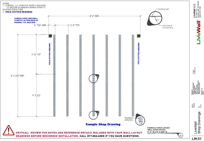
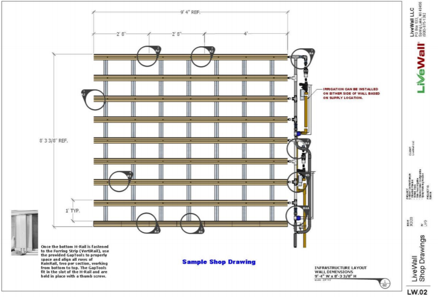
LiveWall’s system is efficient and composed of high-grade materials. The material and components are created with strict quality measures and allow for different compatible irrigation systems from other manufacturers. The components are also clearly supported with various measurements to allow for installation in very diverse projects. Many other structures and companies considered were missing many pieces and required various parties to contribute to completion. The fact that LiveWall contributes most of the components needed to complete the project was very appealing to our team. LiveWall will provide a contractor-sourced breathable hanging protective backing which will allow the building to safely breathe while the living wall is in place. Tyvek Commercial Wrap D is one possible material for the outside. This will accommodate the Acopian wall’s health and dexterity. Once installed the next component of the wall is the furring strips (VertiRail) usually centered at 16” using space wall anchors spaced 12” apart vertically. This will be the main source of connection for the living wall to the brick wall. LiveWall will provide a horizontal slot rain on the bottom row of the wall to hold the bottom row planters in place. This installment is based on the design desired by planter drainage and will allow the planters and rows to properly be aligned. We propose using bottom drain planters which will make the bottom of the slot rail align with the bottom of the furring strips (VertiRail). The installment of rainrails is the most crucial part of the LiveWall because it allows the planters to receive the water. A gap tool will be used to place rainrails in their correct orientations to allow for proper irrigation. The rainrails will be directly drilled through the v-notch with fasteners and anchored to the furring strips (VertiRail). The structures for water irrigation to the living wall are in place and just need to be connected and attached to the water main line. (LiveWall, 2020)
Rainrails come in various sizes, so LiveWall prepares a Rainrail Connector to connect adjacent Rainrails. They will provide a RainRail end plug at the end of each row to stop the water. They will also provide RainRail Adapters for systems with side irrigation which is what we are considering. The RainRail Adapters will be used to connect to the irrigation structure. The irrigation structure or irrigation main line will need to be installed to a ¾” mainline with minimum 25PSI water pressure and 10 gallons per minute water volume to provide adequate water flow. Access to water a source at Acopian is located on the bottom floor and on the second floor. Typical mainline will include backflow preventer with an integrated air gap (required by code), and screen or disc filter. Descaling housing and cartridges may be included to prevent mineral buildup in nozzles or drip emitters. If fertilizer injector is included, follow instructions to dilute fertilizer solution and set rate of uptake. Fertilizer buckets must be placed below the fertilizer injector to allow uptake of solution. All the various components involved with the main line irrigation system is vital for the efficiency and sustainability of the system. (LiveWall, 2020)
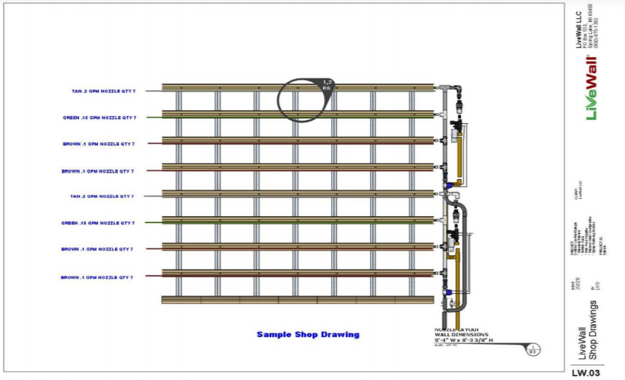
The next step is to mount an irrigation controller and hook up to the electrical supply. LiveWall will provide pipe and fitting which are used to connect irrigation valves to pressure regulators and to RainRails to complete irrigation feed. Once finished, nozzles or drip emitters may be used along RainRails to control water release. Various spray nozzles and drip emitters are provided with desired flow rates. LiveWall will provide brackets to help hold the side irrigation feed. Refer to the installation manual (pg.12) provided by LiveWall for bracket configuration. LiveWall, after the irrigation system is finalized, advises for a facing material to be installed to cover the irrigation system. This, in turn, will cover the unpleasant view of the irrigation system and provide a more aesthetically pleasing view of a material. This material is usually made of aluminum painted sheet metal, cedar, or something similar. (LiveWall, 2020)
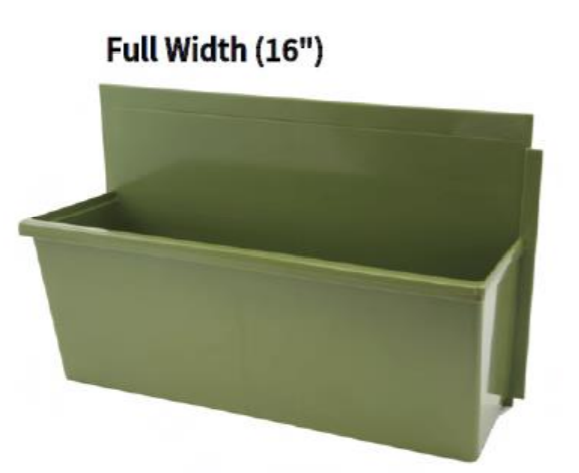
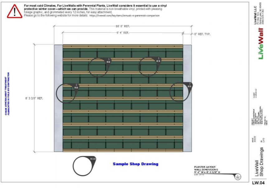
The last component LiveWall provides is the most important for the plants. The planters are the last item to be installed. Planters have an overlapping lip to ensure a tight fit, so they must be installed right to left. LiveWall includes limiting screws for the planters that are in areas of risk for wind damage and theft, the limiting screws are used on planters 20’ above ground and those 8’ or less. With careful placement and proper design requirements, living wall planters will be the perfect fit to host plant life. The standard-sized planters are architectural quality moldings formed from the same polymer as car bumpers (PC/ABS). 100% recycled post-industrial content, 150 mil. thick walls, and no VOC content. Planters come in standard full width 16” and standard half-width 8” to accommodate diverse projects which will be very beneficial to our project. The planter will establish the best sustainable environment for the plants of the wall. (LiveWall, 2020)
In addition to the in-depth analysis of the components of LiveWall, they provide detailed drawings for each available design structure, such as side irrigation and behind irrigation. The drawings are deeply detailed with information on the location of each component and how many per row. They are also detailed for the indoor and outdoor LiveWall placement and provide multiple perspectives of the designs, like front view, side view, and irrigation side view. (LiveWall, 2020)
One key part of our design process has been identifying reliable and trustworthy partners. LiveWall is designated as a professional company for this project because of their capabilities of completing diverse and unique designs. The living wall products from LiveWall contribute to stormwater control, provide habitat for wildlife, reduce cooling loads, and provide many other benefits. (LiveWall, 2020) Most importantly above all, LiveWall provides an in-depth installation guide for projects to be done personally and professionally by contractors. LiveWall provides an in-depth maintenance guide to follow as well to keep the LiveWall up to date. This includes information about how to set the water emitters to drip and the number of times required to water the plants per day based on temperature. It is truly beneficial as it explains fertility management and maintenance required for all 4 seasons around the year, which will be necessary for Easton, Pennsylvania. The preparedness and professional level that LiveWall presents makes it stand out from other competitors in their market.
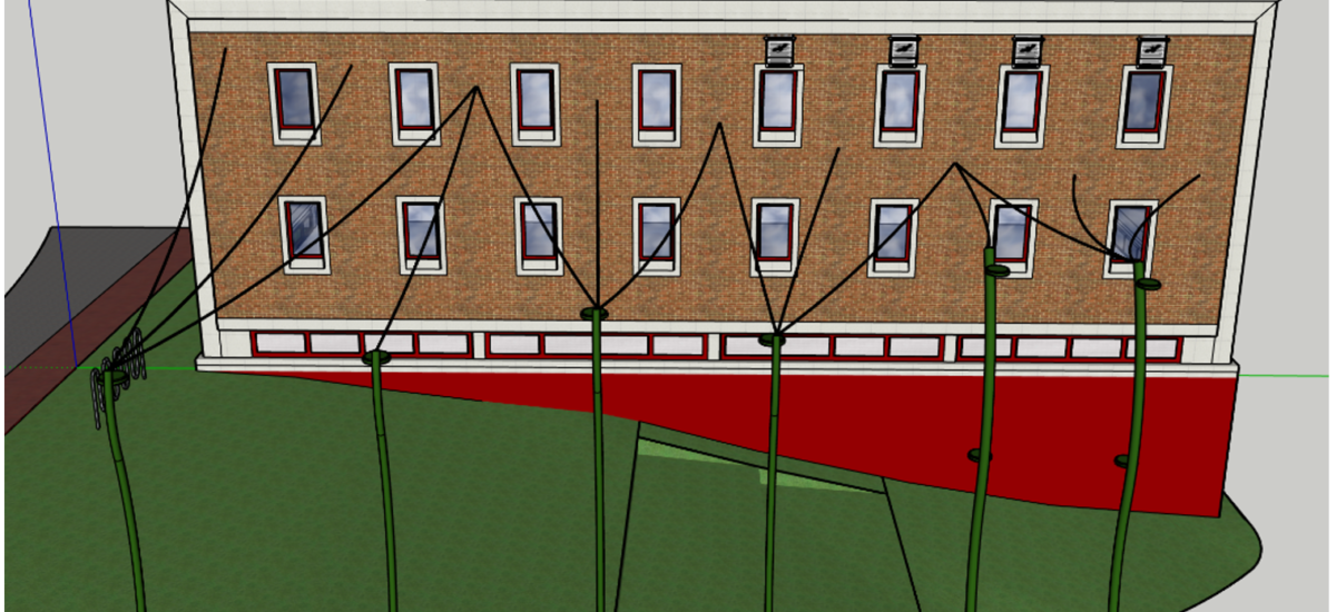
LiveWall was chosen because LiveWall is a professional and reliable company that provides state of the art live walls. Our team is confident that LiveWall will be able to address the design and unique challenges of a living wall as part of Lafayette Gardens. The northeast Acopian wall is a complex project because of the design placement. Our team is proposing to install the LiveWall between the columns of windows. Because of this design, this provides challenges to the wall’s irrigation system and location. Based on the design of LiveWall’s structures it uses the RainRails to transport water horizontally across the wall. Since the proposed Acopian design does not have LiveWall RainRails going fully across the wall it creates a challenge for LiveWall. Variation to the traditional irrigation system must be done to accommodate the Acopian wall design and LiveWall has the reputation and professional ability to complete it.
Lafayette College’s job after the implementation of the living wall is to maintain proper maintenance for the structure to ensure its longevity. Maintenance for the LiveWall system should be completed once every 1-2 weeks. This specifically refers to the irrigation system and the various components involved with it as it is the most vital piece for the plants. The first priority is making sure the irrigation system is not blocked and is fully functional. Also, due to the seasonal changes in Easton, Pa. refer to the maintenance manual provided by LiveWall to understand the changes LiveWall irrigation must undergo during the different seasons.
Calculations for LiveWall
LiveWall provides calculations to ensure the longevity and structural stability of the wall. The information provided about LiveWall and the structure is supported by structural load calculations and wind load calculations. They provide engineering considerations for the height of the structure and the effects of nature on it. In March 2016, UL LLC tested the LiveWall Structure according to TAS-202 “Criteria for Testing Impact and Nonimpact Resistant Building Envelope Components using Uniform Static Air Pressure,” Section 1619 of the Florida Building Code. The structure passed the Uniform Static Air Pressure Test at exterior (positive) and interior (negative) design pressures of 105 PSF. The engineers also provide information with regards to the irrigation system and the amount of water needed to properly sustain the living wall and its plants. (LiveWall, 2020)
Wires
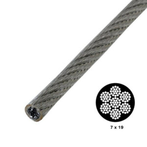
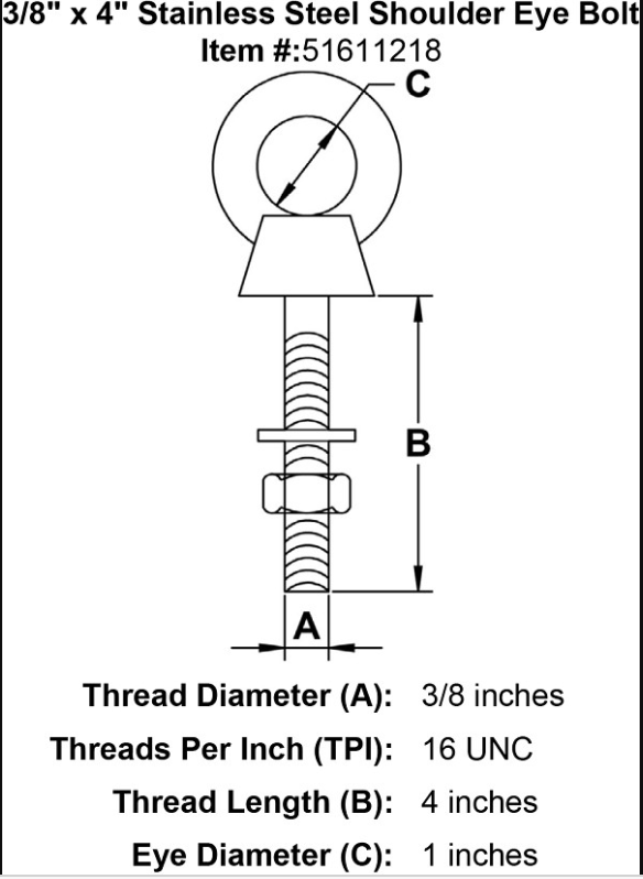
The material considerations for the wires consisted of nylon ropes and vinyl-coated galvanized wire. Our team utilized research from the knot and rope company and US Cargo Control. The ⅛” vinyl-coated galvanized wire from US Cargo Control provides a structurally stable wire that can appropriately hang from the spire to the wall creating the communal space. The vinyl-coated galvanized wire cable is strong yet flexible, perfect for deck railings, porch railings, stair railings- anywhere you want to add a measure of safety without obstructing the view of the area. The vinyl adds an extra layer of protection to the wire while also making it easy to handle. The wire is an excellent multi-purpose cable for both indoor and outdoor use. The industrial uses for the wire provide evidence that it will be very suitable for our design in terms of loading and longevity. The addition of wire clips and wire rope thimbles to help keep stress off the looped end of the wire will be very useful for the project. A warning has been provided through P65 Warnings to alarm some health concerns associated with the metal. The wire is coated to prevent any chemical hazards it may pose to the environment. To ensure more safety and protection, a shrink and shield (nano) and shrink and shield protective coating may be used to cover the wire. This will help with the life of the wire and further protect potential dangers the metal wire poses. Wires will be connected to the brick Acopian wall with 3/8″ x 4″ Stainless Steel Shoulder Eye Bolt. The 3/8″ x 4″ Stainless Steel Shoulder Eye Bolt has a max working load of 1000 lbs and will be a great anchor for the wire. Information must go through Lafayette’s masonry consultant before installation.
Calculations for Wires
Calculations for ⅛” vinyl-coated galvanized wire is provided in the appendix section of the final report. The calculations for the wire are basic structural calculations that ensure the security and stability of the wires. The calculations prove the wire will be able to withstand a weight of 210 lbs directly in the center of the wire rope. The allowable break strength of the rope is 2000 lbs. The wire will withstand a load up to 2000 lbs. In a realistic situation, the wire may experience weather elements like rain, wind, sleet, and snow. A snow weight calculator was used to demonstrate the various weight per inch and weight per foot the wire rope may experience (Snow Weight Calculator, 2020). The greatest weight the wire may experience is from rain and water at about 5.42 lbs for a 50 ft wire with width of 0.125 in and a snow depth of 2 inches. This is around 108 lbs/ ft or 0.009 lbs/ inch. The weight of the rain and water the wires may experience do not reach the threshold to cause failure of the wire.
Spires
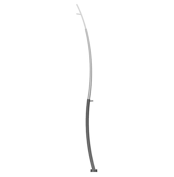
The team considered steel as a potential option for the proposed spire section of the project. Ultimately though, aluminum provided the same results for our project as steel but at a much cheaper cost. Both material considerations originated from the Light Poles Plus Company. Originally simple basic linear spires were considered, but these did not provide the aesthetically pleasing and attention-grabbing design we desired. As a result, our team decided that Valmont Structures was the spire to proceed with, as they provided a structurally safe and abstract spire design. Valmont Structures is a highly recognized company for designing and engineering infrastructure for lighting, transportation, and wireless communications industries worldwide (Valmont Structures, 2020). Valmont Structures has a great reputation for creating customized engineered structures to fit the needs of the customers. The specific spire our team is proposing is called the RTA Idyline Sigma Pole. It is made of seamless alloy aluminum. The structure comes in a variety of heights that are structurally supported with calculations providing information on the effective projected area that may be affected by winds and forces. Caps for the spires will be furnished by contractors to create a design that allows for a wired connection.
Location and design: Note* Locations Start from bottom to top of hill
1st spire: S0-03
2nd spire: S0-03
3rd spire: S0-02
4th spire: S0-02
5th spire: S0-01
6th spire: S0-01
Calculations for Spires
Calculations for the Valmont spires are provided in the appendix of the final report. The calculations for the spires are basic calculations using estimated projected area (EPA) and simple shear stress formulas. The calculations provide information on the forces each different spire may face due to various heights. The northeastern United States normally receives a high wind pressure of about 70 mph according to the American Association of State Highway and Transportation Officials. In order to prove structural stability, the weakest known aluminum metal is 1100-0, with a known shear strength of 9,500 PSI. We tested that aluminum to see if it would fail from the greatest force it receives. Based on the calculations, evidence shows that there is no failure for any spires at any height.
Calculations for Cap of Spire with 3 wires
Calculations for the Cap of Spire with 3 wires are provided in the appendix of the final report. The designed spires created by Valmont Structures do not have a cap that allows for the connection of the wire. As a result, fabrication of the wire caps must be done to accommodate to the spire diameter and design. The fabrication of the spire cap will be the deciding factor to determine the structural integrity of it. The structural integrity of the cap will be determined by the width of the cap loop where the wire rope will tie to. The calculations prove that the minimum amount of diameter of the cap loop needed to be structural safe is 0.0469 inches using the weakest aluminum metal model 1100-00 with an allowable shear stress of 9,500 PSI and the force of 3 wires 445.5 lbs.
Conclusion
The most important value to this project is to make sure the different structures are safe, sustainable, and aesthetically pleasing. The abstract designs of the spires and wires along with the structurally supported calculations provides significant evidence to prove structural integrity. The addition of the spires and wires will help provide the communal space that aligns with our project definition and allow Lafayette College to bring new value to the campus.
Where to Next?
As noted in Chapter 2: Design, Lafayette College should look into more additions of spires to make the space more attractive and break the linear standard model. This may be done by using smaller spires that do not have wire attachments to it. These extra spires will help define the space more and draw people into the space. Another aspect to consider with regards to the spires is the use of lighting. The spires contain the structural capacity to obtain lighting for the surrounding areas, but our team did not have the capacity to analyze the feasibility of powering these lights. We suggest that the next phase of the project consider this as we believe light will increase the safety of the area and make the Lafayette Gardens accessible at night.
Click here to proceed to Chapter 4 – Environmental
To see project calculations click here