
Hardware Design
We were very lucky with out hardware and didn’t have too many problems with it. Most of the parts we chose to use were either used in previous labs or used in projects in previous semesters. There was a project the previous class which used bluetooth communication, thus we were able to use BLE chips which we knew worked for the purposes we needed them, simple one way communication from a master (the key) to a slave (the lock). Coincidentally the chips we had initially looked into were in this groups original parts order, but they had explained in their status updates that there were a lot of unexpected conditions for us, and thus we were able to avoid this timely and costly mistake before parts were ordered. The only part we had to order that was not used in previous semesters was the accelerometer. We went with a Triple Axis Accelerometer which can operate at the same 3.3V as the Microstick || and the PIC32. This particular accelerometer was said to be a x,y,z accelerometer, which we believed would be sufficient since we only want to track horizontal and vertical motion. Additionally, if we were to redesign this project, looking into other Bluetooth chips that might be able to have the slave communicate to the device might be helpful for debugging and status updates. Overall, the parts we initially ordered were able to fulfill their roles and did not make the key too large to be a hand-held portable device, a design concern we had throughout initial design planning. To make the device portable, we chose to use a 3-AA battery holder as our portable power source, converting it’s provided voltage to the 3.3V needed to power the PIC using the voltage regulator found in the parts list.
Obstacles in Hardware
The only unexpected hurdle we faced was mostly about the accelerometer we chose to order. During the first few hours of testing, we began to realize there was a lot more to getting a direction than originally anticipated. The accelerometer is an xyz accelerometer, but we ran into a bit of an obstacle because there is a minimum full-scale range of ±3g. It seems that although we should be able to tell direction in x-,y-,z-coordinates, the minimum range was too large and thus we used it as more of a roll pitch yaw accelerometer. Although we had more time and enough left in the budget to buy a different accelerometer, we ultimately decided to stick with this chip since this orientation may lead to more natural motions, discrete wrist turns rather than large swinging motions, which was a reach goal for future plans. If we were to re-design this project, we would look into alternate accelerometer or possibly even a gyroscope.
Parts List
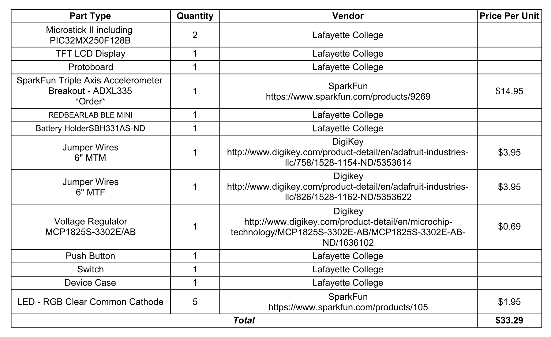
*NOTE: The parts listed above incorrectly state only one BLE Mini chip was used. The project actually used two ReadBearLab BLE Mini devices for bluetooth communication. Additionally, although five LEDs were ordered for the project, only two RGB LEDs were used, one in the key and one in the lock.
Schematics


Finalized Key Device
We decided to create a container for the key device so it would be a more finished and finalized hand-held device. To do this we created an AutoCAD drawing of a box and used Adobe Illustrator to have it laser cut in particle board. See Professor Nadovich to be trained on using the laser cutter or to put in contact with someone who is trained to use it. We have provided the AutoCAD file here for reference.