
System overview
There are 3 main aspects of the train control system. The first aspect is the controller. This is where the user inputs information about the desired route. The second aspect is the wireless link. This sends the data from the controller to each of the 5 stations. The final aspect is the individual stations which decode the controller information and activate appropriate sections of track and set points appropriately.
Block diagram
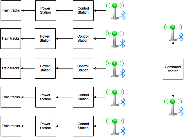
The command station connects to 2 transmitters. These transmitters connect to 5 different stations.
Communication protocols
Bluetooth
Bluetooth works with a master/slave relationship. In our implementation, the master devices connect to the slaves by unique MAC addresses. Unfortunately, the Bluetooth modules from RedBear can only connect to three slaves at a time, so we needed to use two master devices to connect to all five slaves. The user determines the route they want with the User Interface, and the command is sent to all five stations via the Bluetooth. The command format is: Left Station Right Station Direction.
Train station
Each train station interfaces with 3 PICs that control the power to the train tracks. This communication is performed over a 9600/8N1 5V UART connection. Since our PICs worked at 3.3V a simple amplifier circuit had to be built. Each chip can be individually addressed but each packet must contain information about all 3 sections that the chip can control. More information is available on the Track Controller page.
Operation guide
To ensure that all stations are connected to the controller there is a specific way that everything should be powered up. The first section that should be powered up is all of the sub stations. The power section of the train stations should have 3 pulsing green LEDs. If there are not 3 flashing LEDs then the reset button should be pressed. Once all stations are heart beating a green LED the two PICs that are the controller can be powered up. When these devices first turn on the LEDs will be red while the chips are connecting. Once all of the chips are connected the LEDs will go blue. One will go green before the other since it only has to connect to 2 devices, not 3. When there are 2 blue LEDs a test command should be sent. If the stop button is pressed every PIC will be addressed in the system. To verify that every station is connected there should be 3 static yellow LEDs above every PIC on the power stations. There is currently no feedback for a bad packet received.