
The Track Controller had 3 main jobs. The first job was to decode the incoming message from the BlueTooth receiver. The second job was to set the tracks up correctly to get a train safely from one end to the other. The final job of the Controller was to ensure that no train ran over the edge of the track.
Decoding BlueTooth
The BlueTooth connection interfaced through one of the UART channels on the PIC. The PIC would read in the data and look for a sequence of three characters separated by a space. This was the agreed format for the BlueTooth commands. The first character would be the station on the left; either North, Center, or South and the second character would be the station on the right; North, Center, South or Pillar. The last character would be the direction; East or West. The PIC would parse this information using sprintf to ensure that the packet is formatted correctly.
Setting the tracks
There are 2 stages of setting up the tracks. The first stage is to move the points into the correct position. Since a capacitor had to be charged between each change there was a delay of 10 seconds between each switch change. Once the switches were in the correct position the tracks would be energized as appropriate. To set the tracks a packet had to be sent to each station. The packet is formatted as follows:
preamble (0xf1) dest (0x00->0x02) src (0x00) length (0x03) byte0 (0x00->0x3F) byte1 (0x00->0x3F) byte2 (0x00->0x3F) checksum (0x00->0xFF)
The checksum is a bitwise xor of all of the previous bytes. The 3 bytes; byte0 through 2 are used to address different parts of the track. The format of the byte is as follows:
direction (0x0->0x3) speed (0x0->0xF)
The reason that there are 4 directions is because there are some tracks that cross over. When the tracks cross over some of the tracks need to have both rails the same polarity. To make it easier to control the tracks a function was made that would take in the desired PIC destination, direction, and speed of the three bytes.
Safety cutout
To prevent trains from crashing there was a feedback circuit at the ends of every track. There is a reed switch placed at every end of the track. A voltage was applied to one side and the other side was connected to the PIC with an internal pull down resistor. These pins were attached to an input capture that would shutdown the appropriate train track if there was a train detected. Every train had a neodymium magnet glued to the bottom to ensure that the train was detected.
Implementation
Hardware
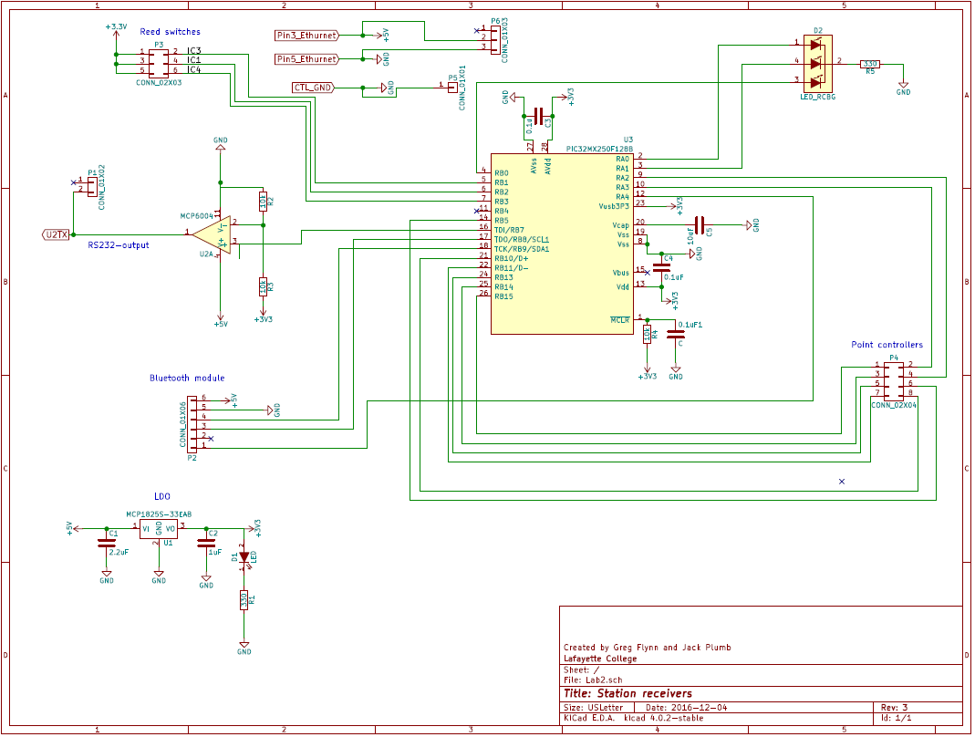
The hardware was built to be able to interface with every train station. This meant that there have to be the ability to control up to 8 different switches, read 3 different reed switches, interface with the 3 PICs at each station and connect to the BlueTooth modules. As previously mentioned the UART signal for the on board PICs was at 5V so there had to be an amplifier. Instead of using a non-inverting setup a simple comparator was used. This had the advantage that it would change as quickly as possible when the UART signal changed. One consideration that is important for the opamp is the slew-rate compared to the baud rate. Since the trains require a baudrate of 9600 (104us/bit) the slew rate can be practically ignored. The slew rate for the MCP6004 (the chip used) is 0.6V/us, easily allowing it to switch voltages in a few microseconds compared to the entire bit period. The second issue was the power supplies. The PIC required 3.3V, any more and there could be long term damage to the chip. Also the voltage for the reed switches had to be 3.3V since there were no more 5V tolerant pins left. This meant that there had to be a LDO voltage regulator on the board to allow for both voltages to be readily accessible. A power LED was added to the other side of the LDO to clearly show when there was power. This was useful for diagnostics as a gross error check to ensure that there was even power being delivered to the station. A second tri-color LED was added to the PIC to allow for a heartbeat LED as well as an option for future developers to provide feedback via the LED colors. In our setup there was a 5V device near to the board which could be used so there was no need to step from a different voltage to 5V. Another addition to the board was the socket for the BlueTooth module. The tx/rx lines were attached to the appropriate pins to allow for the UART to interface with it. The reset pin was attached to a GPIO pin so that it could be controlled in software.
Software
There were 2 threads on every controller as well as 3 ISRs for time critical tasks. The first thread was the heartbeat thread. This is a simple thread that pulses the LED to clearly let the user know if the chip has blocked during a task or frozen.
The second thread was the parsing function. The first task that the thread accomplished was clearing the reset pin to ensure that the BlueTooth receiver was not held in a reset condition. Next it entered the while loop. Inside here it would yield (non blocking wait) until the UART receiver got data. Once this happened it would parse the data looking for 3 characters in a row separated by a space. These three characters would be put into a function that would identify what tracks need to be powered on. The function would call another function called set_speed to address each PIC to ensure that they were set to the correct speed.
The final aspect of the station control was to interface with the reed switches. These were a time critical aspect since when they were triggered a train was about to crash. As a result they were not polled, they triggered an interrupt when they were closed. This allowed the software to quickly shutdown the track if there was a train detected. There are two known issues with the current method. The first problem is the speed of the train. If the train is going fast (above 0x8) it can pass over the reed switch without the train being detected. As a result the train would crash full speed into the buffer. The fix for this is to slow the train down as it comes in to stop just like trains do in real life. This does not address the problem of a faulty line of code. If the developers set the speed too fast for a section of track then the train will crash. The second bug was that the interrupt would sometimes trigger when the train was departing. This would stop the train from being able to leave. A boolean could be added to check the direction the train is traveling in to prevent this safety cutout from happening.