Hardware
i. Real-time Clock
The RTCC hardware module on the PIC32 with an external 32.768 kHz crystal was used to track time in our system. This was configured to alarm every 10 minutes (10 seconds during testing) indefinitely, using the Chime feature. The ISR for this function was used extensively throughout the design to increment other counters used during temperature and wait time calculation.
ii. Soil Moisture Sensor
The soil sensor we used for this project was the Sparkfun Soil Moisture Sensor SEN-13322. This sensor worked as a variable resistor, whose signal we read into the PIC32 with the ADC peripheral. Additionally, to reduce corrosion we configured a digital output on the PIC32 to momentarily power the sensor only when it was being read.
Sensor URL: https://www.sparkfun.com/products/13322
iii. Temperature Sensor
The temperature sensor we used for this project was the Sparkfun Digital Temperature Sensor Breakout board TMP102. Using I2C communication protocol, we were able to read a 12-bit temperature value once an hour (10 seconds during testing).
Sensor URL: https://www.sparkfun.com/products/11931
iv. Solenoid Valve
We used a one-way solenoid valve found on Digikey. This valve was beneficial for our testing due to its ability to actuate without any back pressure. However, it required 9V and approximately 2.3A, which necessitated additional circuitry (as depicted in the system schematic). A power source and power transistor were used to allow the PIC32 to toggle the valve by setting and clearing digital output pins.
Valve URL: http://www.digikey.com/product-detail/en/adafruit-industries-llc/996/1528-1280-ND/5356765
v. Flow Sensor
We used the Liquid Flow Meter found on Adafruit. This sensor was used to monitor the amount of water distributed by the tank while the solenoid was open. The pulsed signal output from the sensor was sent through an op-amp comparator to be read into the PIC. Additionally, Timer peripherals on the PIC were used to determined duration between pulses, and when no flow was detected the screen alerts the user to add water into the tank.
Sensor URL: https://www.adafruit.com/products/828
vi. LCD Screen
We used a 2.2in LCD touchscreen configured for serial communication (found on Adafruit, which was also used in previous labs throughout the semester) as our User Interface for the system.
Software
i. Process Flow
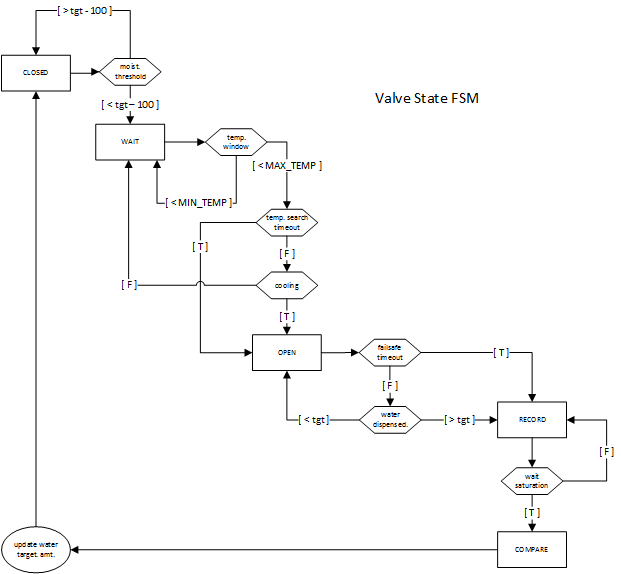
Our system is based off determinations made during each interrupt of the RTCC, occurring every 10 minutes. Here the temperature is updated every hour (default, user-configurable), and depending on the state of the valve FSM, the soil moisture is read, and timeout/failsafe counters are incremented. Below is a diagram of the valve state FSM used to traverse through the watering process.
As shown in the diagram above, starting from CLOSED state if a below-threshold moisture value is detected, the system begins looking for an optimal watering time in the WAIT state. If three negative intervals are detected within a six-hour period, or if timeout has occurred, the valve will advance to the OPEN state, where water is dispensed. Once the target amount is reached, the system advances to the RECORD state. Here the system waits for the soil to saturate, before advancing to the COMPARE state, where the soil moisture is compared with the target value, and the amount of water to dispense for the next watering session updated.
ii. Flicker Removal
To make the GUI more user friendly, logic was added to prevent the screen from flickering. Since the screen does not automatically erase the previous data written to it, the code must be written to perform this task as well as write the new data. The previous information displayed is stored in a separate variable and a comparison is made to the value being updated by the peripherals. If there has been a change in this data, the screen will only overwrite this line and then draw the new data in the same location. After this has been accomplished, the new value is stored in the separate variable to be used in comparisons to the next updated value.

