Week 4
This last week of the project saw us take the final steps to finish up the functionality of our project. Our main goals for this week were as follows:
- Pick up hardware implementation gadgets we had made by the hardware shop including laser mounts and guards for the motion sensors.
- Implement testing using the gadgets.
- Setup and finalize the project functionality.
Laser Mounts
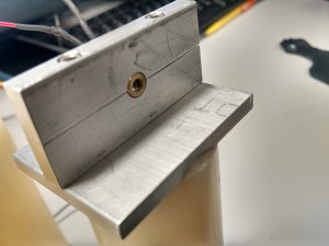
On Thursday, we received our laser mounts from the hardware shop. These were designed and requested by Preston in week 3. The mounts greatly improved our testing procedure as they brought an extra degree of stability that was welcome. The mounts are pictured below.
In addition. Raji resoldered the connections to the lasers for length and a sturdier connection. Heat shrink tubing was also used to cover the joints between the two different wires. This process required a soldering iron, 24 gauge wire and an heat gun.
Sensor Limiter
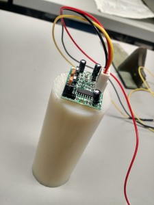
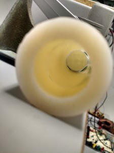
On Friday, we received acrylic tubes we had requested from the hardware shop to limit the sensitivity scope of our Motion Sensors. The sensors initially had a spherical scope that was much too wide for the application we had in mind. Our plans were to suspend motion sensors above each seat at the table to be monitored and the relatively large default scope would keep picking up readings from other seats. To combat this, we used the tubes to limit the scope of the sensors strictly downward. The Sensor + Tube setup in question are presented below.
From Top From Front
Mounted Hardware Sensor Testing
Laser Link
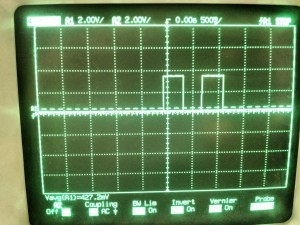
After installing the lasers into our mounts and positioning the phototransistors and the corresponding circuits in place, we ran some hardware tests. Results were as expected. The phototransistors have a low voltage output if detecting the laser and vice versa, by blocking the laser a high output is observed. Scope output results from the phototransistors are shown below are shown below.
- The picture shows the output from the Laser link circuit as Preston walked through simulating a person walking through a door. The first pulse is the front laser being broken, and the second pulse corresponds to the second laser.
Motion Sensors
Raji ran similar tests with the adjusted Motion Sensors and we got the expected results. A low signal is output from the sensor when nothing has been detected in the field of view and a high is output for a duration of 10 secs when movement is detected. We are using this property to determining if the seat being monitored is empty or not.
Putting it Together
Preston built the voltage regulator/laser and phototransistor circuits of the project. The former being the “transmitter” and the latter the “receiver”. The voltage regulator used a LM317TO-220 which stepped the 9V battery down to ~3.3 for the laser. The phototransistor circuits outputted a high voltage (3.3V) when the laser link was blocked. This is similar to the circuitry implemented in lab 5.
Having gotten successful hardware testing out of the way, for the final part of this week, we focused out efforts on the software side of things. We used the outputs from our laser link to trigger interrupts and figure out if somebody was going or leaving. And we used our motion sensors to monitor table activity. The interrupts have been giving us severe trouble however not triggering when expected.


