
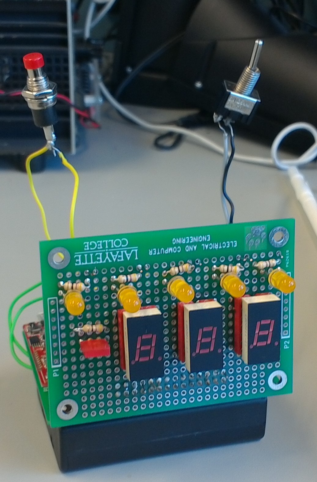


Seven Segment display
The seven segment display was set up using using a cathode to time division multiplex the screens. This allowed wiring to be shared. The display was also accompanied by a single LED that allowed for a negative sign. The display constantly displayed the value of the player’s current score, which was set and controlled by the host module.
The Buzzer
The buzzer was a push button wired to an input capture which caused an interrupt when it was detected. The buzzer was also wired to an RC circuit to debounce it. The originally intended operation of the buzzer was as follows: The player would buzz in, putting the buzzer into a “locked and waiting” state and send a push message to the host. In the lock and waiting state the button would no longer respond and the Buzzer LED indicator would be off. Once the host module received and processed what could potentially be multiple button presses, it send out a first signal to whomever buzzed in first and a lock-down signal to all the other buzzers. The lock down signal would put any player module into a state similar to “locked and waiting” from any previous state. If a player module received notice from the host that it was the first player to buzz in, the buzzer would lock up but also turn on the indicator light. In order to return to the original state and reanble the buzzer the player would have to receive a clear signal from the host.
Battery based operation
We decided to go with 3 AA batteries for combined voltage of 4.5 volts. This was because most of our equipment in previous labs ran at 3.3 volts and the Bluetooth chip said its minimum voltage was 3.3 volts. The extra voltage also meant that the batteries could lose some charge and we could still be at optimal voltage. To control the actual voltage, we used an MCP1825S-3302E/AB voltage regulator. Another aspect to having the player module be portable and cheap to construct was that we had to avoid using the microstick on the player module. To do so we would program the PIC using a microstick and then plug it directly into our circuit. However our research determined that there are specific external parts required by the PIC32 that allow it to operate. These external parts are usually provided for us by the microstick, so we had to include them in our design as well as seen below. To prevent constant use of the battery a switch was installed. We thought about utilizing an idle mode to further conserve battery life but failed to get to it within time constraints.
Peripheral Bluetooth
The Bluetooth chip while being the exact same Red Bear chip used in the host would be flashed with completely different firmware. This firmware, called Biscuit, allowed much simpler operation and lower power consumption characteristic of Bluetooth LE peripheral devices. Sending in UART to the chip’s Rx pin would cause an immediate transition of the exact UART message sent in. Sending a message to this device would cause the exact message that was sent to come out of the Tx pin. This simplified communication from the player module stand point as we could treat the chip exactly like a terminal as done previously. The actual commands used were as follows.
| Command | Function |
| <Target ID> <Sender ID> a <Points> | adds <Points> to the player’s current score |
| <Target ID> <Sender ID> s <Points> | subtracts <Points> to the player’s current score |
| <Target ID> <Sender ID> p <time> | sent by player to host indicates a button was pressed and <time> indicates the local time that it was pressed |
| <Target ID> <Sender ID> c | Clears the current state and start waiting for buzz |
| <Target ID> <Sender ID> l | Locks down the player module preventing button presses |
| <Target ID> <Sender ID> r | Resets the player module |
Relevant Schematics

Plan B
We failed to get the host module to read commands from the player module in time which prompted a change in functionality from the player module stand point. Instead of locking down and waiting for a response from the host, when the button was pushed on the final player module it would light up the LED. The host would then select who they believe buzzed in first and lock out the other player modules which turned off their LEDs. The player modules would still wait for clear and handle clear and score setting accordingly.