
The host module is comprised of a battery pack, the PIC32 (the PIC32MX250F128B), a touch LCD screen (the Adafruit 2.4″ TFT LCD) and a Bluetooth 4.0 LE chip (the RedBearLab BLE Mini).
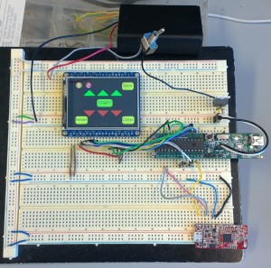
The specific connections between the PIC32 and the peripheral devices are detailed below.
| PIC32 Physical Pin | Software Pin | Connection |
| 25 | RB14 | CLK pin on LCD screen |
| 22 | RB11 | MOSI pin on LCD screen |
| 6 | RB2 | RST pin on LCD screen |
| 5 | RB1 | CS pin on LCD screen |
| 4 | RB0 | D/C pin on LCD screen |
| 12 | RA4 | X+ pin on LCD screen |
| 2 | RA0 | X- pin on LCD screen |
| 3 | RA1 | Y+ pin on LCD screen |
| 10 | RA3 | Y- pin on LCD screen |
| 17 | RPB8 | UART RX pin in from Bluetooth chip |
| 18 | RPB9 | UART TX pin out to Bluetooth chip |
| 26 | RB15 | Reset Pin on Bluetooth chip |
The LCD screen and the Bluetooth are both also connected to power (through the voltage regulator) and ground.
The host module’s program was designed with three main functions in mind:
- Establish connections with the player modules
- Select a player and transmit data to just that player
- Select what value to send to the selected player
The LCD screen has touch capabilities, which are used to select the player, adjust their points earned and send those points to that player.
Bluetooth 4.0 LE is a form of Bluetooth communication that has distinct central and peripheral components and firmware. Central chips use a Host Controller Interface (HCI) protocol; this is the kind of chip the host module used. This required additional software to properly translate the data we wanted to send to the players into the expected format for the HCI protocol. The final Bluetooth chips we used were purchased from RedBearLab. These chips had a beta release of an HCI library to support their operation as central modules. Most of the functions in this library were written to be used with an Arduino board, so we needed to modify it to function with our PIC32 device.