Project Proposal
FARMSENSE 2027 Preliminary Project Proposal
Karen Shimp, Fletcher Crean, Maya Maynard, Quincy Hughes, Sean McLoughlin, Samuel Owens, Haoxuan Shi, Denys Didenko and Xiaomeng Shi*
*Visiting Assistant Professor in the Electrical and Computer Engineering Department
Abstract
Lafayette College’s Engineering Division has requested that the 2027 senior class work to design a FARMSENSE (Farm Automated Recording, Monitoring, and Sensing for Environmental Nurturing and Sustainable Ecosystems) system to deploy at LaFarm. The main objective of the proposed system is to create an adaptable automated system that can help with both drying produce and growing plants in one greenhouse. The system will contain all of the items necessary for powering, sensing, and controlling the shades and vents, with potential for also controlling the irrigation and sprinklers. This system is composed of a solar panel, battery, comprehensive sensor system, automated devices, and an interactive interface.
1 Motivation
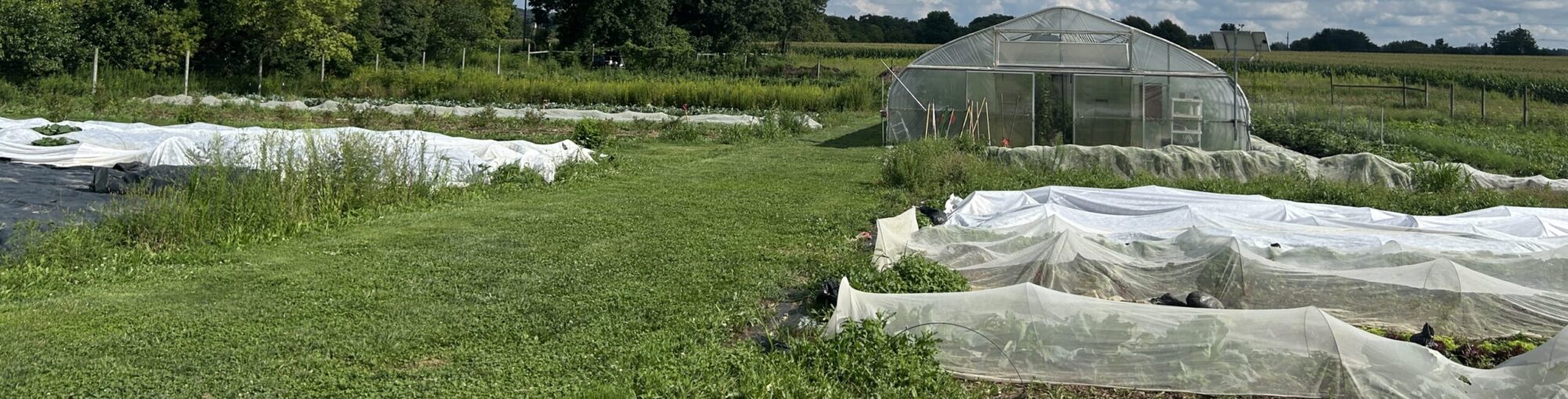
LaFarm integrates curriculum and practice in sustainable food and agriculture for the Lafayette campus [1]. They grow food for the dining halls as well as the larger community. Constant monitoring of the greenhouses and manual adjustments of equipment place strain on the LaFarm staff. Human error in this process leads to wasted resources and can lead to nonoptimal conditions for growing or drying plants. The solution: FARMSENSE, an automated greenhouse system that can independently control parameters like temperature, light, and humidity by adjusting the vents, sprinklers, and shades. Our proposed technology would improve resource management, crop yield, and labor demands. It will align with LaFarm’s goal of sustainability by utilizing solar panels and improving the use of resources such as water and energy.
2 Design Objectives
2.1 Physical Structure
The FARMSENSE system will consist of several distributed subsystems, including environmental sensors, actuators, a central controller, a user interface, and a solar-based power system. These components will be physically distributed throughout the greenhouse and electrically connected to a central control unit (PLC or Microcontroller). The controller will act as the centerpiece of the system and will be responsible for receiving sensor data, processing that information based on its programming (PLC, arduino, or C), and controlling the appropriate actuators [9].
Environmental inputs will include measurements such as soil moisture, ambient temperature, relative humidity, light intensity, outside weather conditions, and a flow rate sensor. These measurements will provide the controller with information about the current state of the greenhouse. Based on predetermined operating ranges and control thresholds, the controller will activate or adjust devices such as ventilation fans or vents, irrigation valves or sprinklers, and automated shades [9]. For example, if soil moisture falls below an acceptable threshold, the controller can activate the irrigation system until it restores the desired moisture level. Likewise, excessive temperature or light intensity could cause the system to open vents or deploy shading. In this way, FARMSENSE will operate as a closed-loop control system in which environmental conditions are measured, compared against desired conditions, and automatically corrected through actuator operation [9].
The physical layout of the system will be modular rather than concentrated within a single enclosure. This allows individual sensors and actuators to be positioned where they can most accurately measure or affect greenhouse conditions. The primary controller and user interface will be mounted at an accessible location on an interior greenhouse wall, allowing users to view system status, sensor readings, warnings, and potentially modify control setpoints without interfering with the growing area. The central electronics enclosure will also provide a convenient location for wiring terminations, communication hardware, voltage regulation equipment, fuses, relays, and other supporting circuitry.
Environmental sensors will be placed according to the variables they are intended to measure. Soil-moisture probes will be positioned within the growing soil near the root zones of representative plants. Temperature, humidity, and light sensors will be mounted on a wooden or 3D-printed support structure above the soil and near plant height [9]. Placement at this level is important because conditions near the crop canopy may differ from conditions near the greenhouse ceiling or wall. Sensors will also be positioned to minimize measurement errors caused by direct sprinkler spray, unusual shadows, concentrated airflow, or direct contact with structural surfaces [9].
An exterior weather-monitoring unit will be installed on or above the greenhouse roof. The unit may include an anemometer as well as other outdoor sensors for measurements such as wind speed, exterior temperature, humidity, and atmospheric pressure. External wind measurements could be especially important when controlling automated vents because the system may need to prevent vent operation during excessively high winds [13]. Outdoor measurements can also be compared with interior measurements to improve the control strategy.
The irrigation system will be routed above the crop area and supported from the greenhouse structure using metallic cable, brackets, or another corrosion-resistant mounting method. Sprinkler or irrigation lines will be positioned to provide sufficient water coverage while minimizing interference with other greenhouse equipment. Automated shades and vents will be installed along appropriate ceiling and wall surfaces and connected to motors, servos, linear actuators, or other mechanisms capable of receiving commands from the controller [9].
Because FARMSENSE will operate in a humid and potentially wet agricultural environment, environmental protection will be an important part of the mechanical design. Vulnerable electronics will be installed inside weather-resistant enclosures designed to protect against water, soil, dust, fertilizer residue, and accidental contact. Where practical, enclosures should use sealed cable penetrations, gaskets, and strain relief to prevent moisture from entering around wiring. Sensitive circuitry should also be positioned away from direct irrigation paths and areas where condensation is likely to accumulate.
Wiring will be routed along the greenhouse structure in an organized manner using conduit, cable trays, clips, or similar supports. Separating low-voltage sensor wiring from higher-current actuator wiring will help reduce electrical noise and make troubleshooting easier. Connectors should also be selected so individual sensors or actuators can be replaced without requiring the entire wiring network to be removed. This modular design will allow the system to be repaired, expanded, or modified in the future.
Overall, FARMSENSE will function as a distributed network of sensing, control, and actuation devices spread throughout the greenhouse and connected to one central controller and user interface. Rather than functioning as a single compact device, each subsystem will occupy the location most appropriate for its function while remaining part of one coordinated automated control system [9].
2.2 Power
Sustainability is a major design priority for FARMSENSE. In addition, the greenhouse’s location on the farm has limited access to existing electrical infrastructure. For these reasons, the system will use an independent photovoltaic power system capable of generating, storing, regulating, and distributing the electrical energy required by the greenhouse control system [8].
A solar photovoltaic panel, or potentially multiple panels depending on the final load calculations, will be mounted on or adjacent to the greenhouse. Panel placement will be selected to maximize solar exposure while minimizing shading from trees, nearby buildings, greenhouse structures, or other obstructions [8,10]. Important design variables will include panel orientation, azimuth angle, tilt angle, seasonal sunlight variation, regional weather conditions, and expected solar irradiance [8,10]. These factors will be used to estimate the amount of electrical energy that can realistically be generated on both typical and low-sunlight days [10].
The solar panel will generate DC electrical power [8]. Rather than supplying that power directly to the greenhouse components, the panel will first connect to a solar charge controller. The charge controller will regulate the energy supplied to the battery and prevent conditions such as battery overcharging or excessive discharge. An MPPT, or Maximum Power Point Tracking, charge controller may be considered because it can improve the amount of usable energy extracted from the photovoltaic panel as lighting and temperature conditions change throughout the day.
A rechargeable battery bank will provide energy storage between the solar panel and the FARMSENSE loads. The battery will allow the system to continue operating at night, during cloudy conditions, and during periods when instantaneous system power demand exceeds photovoltaic production [8]. Battery capacity will therefore be selected based not only on the maximum power demand of the system but also on the total energy consumption over time. The battery should provide enough stored energy to operate essential components for a predetermined period without sufficient sunlight.
The system’s electrical load will be divided into continuous and intermittent loads. Components such as the microcontroller, communication hardware, user interface, and environmental sensors may operate continuously and therefore contribute to the system’s baseline power consumption. Actuators such as irrigation pumps, solenoid valves, vent motors, and shade motors may consume significantly more power but operate only for short periods. Their duty cycles will therefore be included when calculating total daily energy demand.
For example, the energy requirement of each device can be estimated using
E=Pt
where E is energy in watt-hours, P is device power in watts, and t is the number of hours the device operates per day. The daily energy requirements of all components can then be summed to estimate the total system demand:
Etotal=∑Piti
The photovoltaic array and battery can then be sized with an additional safety margin to account for wiring losses, voltage-conversion losses, battery inefficiency, cloudy weather, component aging, and future system expansion [10].
Because many FARMSENSE components, including sensors and microcontrollers, will likely operate from low-voltage DC supplies such as 3.3 V, 5 V, 12 V, or 24 V, the system will not necessarily convert all photovoltaic power into AC [8]. Instead, DC-DC converters and voltage regulators can provide the required voltage levels directly from the battery system. This approach reduces unnecessary conversion losses. If an actuator or pump selected later in the design requires conventional AC power, an inverter can be incorporated specifically for those loads [8].
Electrical protection will also be incorporated into the power subsystem. Appropriate fuses or circuit breakers will protect individual branches against excessive current and short circuits [5]. Disconnect switches should be included between major components such as the photovoltaic array, charge controller, battery, and load distribution system so sections can be safely isolated during maintenance [5]. Wiring will be sized according to expected current, voltage drop, and cable length, particularly because sensors and actuators may be distributed across a relatively large greenhouse.
Battery and power-control electronics will be installed in a protected enclosure away from direct irrigation, standing water, and excessive heat. Outdoor photovoltaic wiring and connectors will be selected for environmental resistance and long-term exposure to sunlight and moisture. Grounding and electrical protection will also be considered as the design progresses, particularly because the photovoltaic array and external weather sensors may be mounted on the greenhouse roof [5].
The final photovoltaic system will therefore be sized by comparing the greenhouse’s expected daily electrical energy consumption with the amount of solar energy realistically available at the installation site [8,10]. The design goal will be to provide enough generation and stored energy to operate FARMSENSE reliably without requiring a permanent connection to the electrical grid, while maintaining sufficient reserve capacity for nighttime operation and periods of reduced sunlight [8].
2.3 Data Collection and Sensor Input
Data collected about the farm’s current operational state will be taken via an array of input sensors measuring relevant parameters to best influence the system and allow for the most optimal adjustments to be made to system outputs. System sensor types have been chosen based on information collected from LaFarm manager Josh Parr’s insight on relevant parameters typically taken into consideration in greenhouse management and research done to determine helpful data points often considered in the operation of similar systems beyond LaFarm. Our current sensor array design intends to include: an anemometer for wind speed detection, an IR camera for blanket surface temperature detection, a humidity sensor for general humidity detection, a light sensor for irradiance detection, and a moisture/temperature sensor for soil moisture level detection.
The anemometer is intended to collect wind speed data to influence the control of the rafters and vents around the greenhouse for the purpose of managing air mobility and minimum air speed. Air mobility was mentioned as an extremely important metric indicating the greenhouse environment’s ability to perform optimally when acting as a drying chamber for grown crops. The currently active semi-automated greenhouse utilizes anemometer data taken from outside the greenhouse to measure the safety of rafter adjustments, but does not have the ability to adjust rafter state based on the current internal wind speed. Data collected from the anemometer is intended to be read as an analog input to the microcontroller PLC directly indicative of currently measured wind speed.
An infrared camera is intended to be used for mass surface temperature measurement across the greenhouse when being used as a drying chamber to allow for optimal operation of cooling and heating activation at the system output. Temperature management and the ability to maintain optimal temperature were indicated to be pivotal to drying efficiency in both independent research and conversations the group had with Josh. To avoid forcing farm workers/volunteers to place sensor arrays around the drying stations each time a new setup is employed, the infrared sensor takes advantage of the likelihood of clear vision of crops on the drying rack to measure all temperatures at once and allow the microcontroller to make necessary adjustments to temperature-controlling outputs. Data from the infrared camera will come in the form of periodically sampled images taken by the camera, which will be fed into a model to interpret collected data accordingly. Independent research has been done to determine that a plethora of open-source model availability within this area could be used to accelerate the development of image processing and data collection [11, 12].
Humidity detection was also found to be extremely important in both independent research efforts and conversations between the group and farm manager Josh. Humidity was found to play a major role in the efficiency of both drying efforts when the greenhouse is intended to operate as a drying chamber and when acting as a standard greenhouse for plant germination and growth. Humidity sensors will be placed periodically throughout the greenhouse in a grid formation to increase resolution of collected data and produce a more complete picture of the humidity state throughout the greenhouse. Sensor data will be processed into a single datapoint to indicate humidity state via the microcontroller and inputs will be managed by an analog switching circuit.
Irradiance detection will be done to determine the current light level within the greenhouse, which has a major impact on plants’ growth rate and maximum size when the greenhouse is used for plant growth. Measured irradiance will be passed to the microcontroller via an analog signal and will be used to directly determine the system’s decided optimal shade position state.
Soil moisture and temperature sensors would be placed in potted plants when the greenhouse is intended to operate as a growth chamber for new and existing plants. Ideally, sensors could be placed adjacent to each plant, allowing for maximum relevant resolution of both soil moisture and temperature, but feasibility for this goal would be largely based on the consistency of the number of plants placed in the greenhouse for each harvest. Soil moisture and temperature are massively indicative of organisms’ ability to grow successfully and sensor input would be extremely indicative of the necessary output state of watering and temperature control actuators as well as potential plant growth expectancy calculations.
2.4 Data Processing and Management
Data is intended to be processed within the primary microcontroller PLC, which processes all input sensor data and actuator control signals. Some sensors, including the IR camera and array-based sensor implementations, will require auxiliary processing aids, such as supplemental microcontrollers for IR image processing or input switching managers – likely aligning with standard embedded system implementations such as I2C – for management of massive sensor arrays. Processing of data from massive sensors may also require the implementation of auxiliary microcontroller units to meet demands for compute magnitude. The primary microcontroller PLC implementation will be the main controller for all analog and digital inputs as well as digital output signals used to control actuators.
Interpretation of each system input and determination of intended output states is based on the intended operation mode to be set via the user interface intended to receive information regarding the greenhouse’s current operation state (drying/growing) and the subject plant to be managed to determine operational behavior.
2.5 Actuators and System Output
The system will manage outputs using digital outputs from the primary microcontroller PLC. Optimal outputs will be sent via microcontroller digital I/O and used to control actuators to optimize plant growth or the drying process, depending on user settings. Planned actuators include greenhouse vents/rafter control, greenhouse shade motors, and valve control to manage water output through the installed sprinkler system.
Greenhouse vents will be controlled to optimize airflow through the greenhouse, allowing natural ventilation through the area to boost plant growth rate and drying rate for subject plants. A servo motor will be installed on the rafter control chain to allow the microcontroller to manage the current state dependent on specific airflow requirement for optimal performance. Servo motors used for this purpose will be controlled via PWM signals indirectly digitally driven from microcontroller output.
Greenhouse lighting will be controlled via servo motors connected to the drive chain for shades attached to the side of the greenhouse to control irradiance for plant growth optimization. Servo motors controlled for this purpose will be controlled via PWM indirectly driven by microcontroller digital I/O.
The sprinkler irrigation system will be managed by an electronically controlled valve system used to optimize the ambient humidity and soil moisture level for both drying and growth processes. Valves will include feedback flow rate sensors to more accurately determine the output water volume, looped through the primary microcontroller to determine how the microcontroller’s digital output state is affecting true flow rate output. Valve control will likely be managed via PWM control determined via digital feedback monitoring and applied to the valve input.
3 Design Metrics and Constraints
This system is physically constrained to the empty greenhouse on the far side of LaFarm.
Temperature sensors have to measure the temperature throughout the room, specific to each area of the greenhouse to optimize the data collections. Moisture sensors have to do the same but for moisture in the greenhouse. The electronics will be exposed to dirt, humidity, water from the irrigation, variation in temperature. During seedling operation, the system must be capable of maintaining ambient temperature between 68 F and 77 F. For the crop drying process, the humidity levels must be maintained below 60%. The light and moisture control thresholds will be adjustable depending on the specific crop needs.
Environmental data will be logged at least once every five minutes. The solar and battery system should provide at least 48 hours of sensing and logging without active solar generation. The electronics enclosures must meet at least IP65 protection against dust and water. Other restrictions include the budget of 5000$, locations where sensors can be mounted, the accessibility of solar power, electrical and agricultural safety standards, and the compatibility of the selected sensors, controller, and user interface.
Another constraint is the seasons and measuring the impact of our solution. Since the class is constrained to one year it will be difficult to measure the impact of our solution over the growing season. Due to that a testbench must be made which measures the benefits of the project (like water usage). It may also be difficult to implement in LaFarm due to the ground freezing over in the winter so final implementation must wait until the spring when the ground thaws.
3.1 Backup Plan
As there are concerns about finishing the project by the end of the year and we want to have a finished system, there are some additional considerations for this project. If we run into time constraints, we will first shrink the scope of the project to focus on the internal automation for the greenhouse and not the larger irrigation project as well. If this still seems infeasible, the focus of the project will be on data collection to give LaFarm management more insight into their growing season and the conditions of the greenhouse. This will still achieve our goal of helping LaFarm use their resources efficiently and increase crop yield; It will just require monitoring by the staff of LaFarm.
4 Relevant Codes and Standards
During the design process, our team will prioritize the safety and well-being of the clients, users, and the team itself. We plan to refer to the following guidelines and standards: NEC Article 690 (Solar Photovoltaic Systems) [7], NEC Article 706 (Energy Storage Systems), NEC Article 547 (Agricultural Buildings), UL 508A (Standard for Industrial Control Panels), UL 1310 (Class 2 Power Units), ASABE EP406 (Heating, Ventilating and Cooling Greenhouses), ASABE EP458 (Field Evaluation of Microirrigation Systems), ASABE S612 (Energy Auditing of Agricultural Operations), FCC Part 15 (Class B / Unlicensed Sub-GHz), IEEE 802.11 / IEEE 802.15.4, USDA Food Safety Modernization Act (FSMA) / Produce Safety Rule (21 CFR Part 112), EPA Worker Protection Standard (40 CFR Part 170), the Lafayette College Environmental Health and Safety (EHS) Guidelines, and the Lafayette ECE Laboratory Safety Policy and Guidelines [5,6,14,15].
5 Concepts Applied From Other Courses and to Learn
5.1 Concepts from other courses
As this course is designed specifically for seniors seeking an Electrical and Computer Engineering degree, the design will apply concepts from our previous courses in the ECE and CS departments. The following courses [2] provide the foundational knowledge relevant to the design and implementation of FARMSENSE:
- ECE 414 – Embedded Systems: This course provides fundamental knowledge about Microprocessors such as the Raspberry Pi Pico and multiple communication protocols with sensors, which is directly applicable to the design of the sensor fusion part in FARMSENSE.
- CS 205 – Software Engineering: This course covers software design processes and team-based development, which will guide the structured implementation of the monitoring design.
- ECE 322,323 – Design of Solid State Circuits I & II: These courses provide knowledge about complex circuit design and PCB design, which is essential for implementing circuits into a larger system.
- ECE 331, 332 – Signals and Systems, Communication Systems: These courses provide the theoretical basis for signal processing and wireless communication, which is a direct support towards the signal processing system in FARMSENSE.
- ECE 433 – Industrial Electronics and Control Systems: This course provides the basis for open-loop and closed-loop system performance analysis, which is one of the important analyses we made at LaFarm.
- ES 101 – Introduction to Engineering: This course introduces the Engineering Design Process, including various useful concepts in the system-level planning of FARMSENSE.
5.2 Concepts to learn
-
- Data Logging and Caching System: Although we did not learn how to log and cache data directly, it should be relatively easy to implement the caching and data logging system. It is also beneficial to learn about the standard way to maintain the file that contains the cached data, as our system will run in a long-term environment [3].
- Dashboard and Interface Design: It is difficult to design a good interface where every critical variable can be easily controlled by a user that is not familiar with the whole system and lacks prior knowledge; some standards, testing, and loop engineering should be introduced here.
- Agricultural Sensor Calibration: The sensors in a real greenhouse environment might encounter some randomness in terms of data measurement, so it is necessary to introduce calibration in both the software and hardware side of the FARMSENSE project [4].
- Power Management and Battery with Solar Panels: The FARMSENSE project’s power relies mostly on the power from Solar Panels which is stored in the batteries. It is critical to create a working and effective solar panel power conversion system using advanced Engineering knowledge.
6 Unit Testing Procedures
6.1 Sensors
- Reading from sensors
- Moisture
PASS: We can read voltage from the sensor.
FAIL: Voltage cannot accurately be read from the sensor.
- Temperature
PASS: We can read voltage from the sensor.
FAIL: Voltage cannot be accurately read from the sensor.
- Lighting
PASS: We can read voltage from the sensor.
FAIL: Voltage cannot be accurately read from the sensor.
- IR Camera
PASS: The images from the camera correctly depict and record temperatures throughout the greenhouse.
FAIL: Images cannot be received from the camera, and temperatures cannot be recorded.
- Anemometer
PASS: We can read voltage from the sensor.
FAIL: Voltage cannot be accurately read from the sensor.
- Sensor data storage: Ensure the data from the sensors is correctly stored.
PASS: The historical data from sensors is successfully stored and accessed.
FAIL: The historical data from sensors is not successfully stored or cannot be accessed.
6.2 Controller
- Sensor Reading: Ensure the controller receives signals from the sensors.
PASS: The controller receives appropriate signals from the sensors.
FAIL: The controller does not receive appropriate signals from the sensors.
- Actuator Control: Ensure the controller can control the actuators
PASS: The controller can appropriately control each actuator.
FAIL: The controller can not control some or all of the actuators.
6.3 Power
- Reliability: Ensures the power system can reliably and continuously power the sensors, actuators, and controller at all times.
PASS: The power system has no major interruptions when running for a continuous 24 hours.
FAIL: The power system has major interruptions when running for 24 hours continuously.
- Power Sufficiency: Ensure the power system has enough to power all components of the system.
PASS: The power system can power all components.
FAIL: The power system cannot power all components.
7 Estimated costs
Based on our preliminary research, we are estimating a budget of $5000. The items we are expecting to purchase include a variety of sensors and data reading devices, various output devices such as agricultural heating pads and sprinklers, as well as a user interface and a PLC or microcontroller. We also plan to purchase a solar panel and battery for accumulating and storing more power and a Wi-Fi bridge in order to be able to connect our system to the internet. We will also need to purchase irrigation hoses to implement an improved irrigation system.
8 Website Access
To display information about the project and updates about our Senior Design Project, we have a FARMSENSE website. Here you can find information about the design team members, the work of each sub-group within the project, and documentation about preliminary designs and proposals. This website will be updated on a regular basis by all group members, overseen by Sean McLoughlin. The website can be found at https://sites.lafayette.edu/farmsense/.
9 Timeline
Milestones:
- Preliminary Project Proposal (9/18)*
- Design prototype and testbench (10/10)
- Order prototype/test-bench parts list (10/15)
- Run the first system test on the prototype (11/13)
- Design Proposal (11/20)*
- Preliminary Design Review (12/7)*
- Mid-Year Progress Report (12/14)*
* hard deadlines given by Professor Shi.
10 References
[1] Lafayette College, “LaFarm,” Lafayette College, 2026. [Online]. Available: https://garden.lafayette.edu/. [Accessed: Sep. 18, 2026].
[2] Lafayette College, “ECE – Electrical and Computer Engineering,” in 2026-2027 Catalog, 2026. [Online]. Available: https://lafayette.smartcatalogiq.com/en/current/catalog/courses/ece-electrical-and-computer-engineering. [Accessed: Sep. 18, 2026].
[3] “Data Logging With Raspberry Pi Pico,” Instructables, 2026. [Online]. Available: https://www.instructables.com/Data-Logging-With-Raspberry-Pi-Pico/. [Accessed: Sep. 18, 2026].
[4] Rika Sensor, “How To Calibrate Agriculture Moisture Sensors For Reliable Field Data?,” Rika Sensor, May 27, 2026. [Online]. Available: https://www.rikasensor.com/a-how-to-calibrate-agriculture-moisture-sensors-for-reliable-field-data.html. [Accessed: Sep. 18, 2026].
[5] International Code Council, “National Electrical Code (NEC) Solar Provisions,” in International Solar Energy Provisions, 2021. [Online]. Available: https://codes.iccsafe.org/s/ISEP2021P1/national-electrical-code-nec-solar-provisions/ISEP2021P1-NEC-Sec690. [Accessed: Sep. 18, 2026].
[6] National Fire Protection Association, “NFPA 70®: National Electrical Code®,” NFPA, 2026. [Online]. Available: https://www.nfpa.org/codes-and-standards/nfpa-70-standard-development/70. [Accessed: Sep. 18, 2026].
[7] National Fire Protection Association, NFPA 70 – Article 690 – Solar Photovoltaic (PV) Systems (2017 Edition), digital copy via Scribd. [Online]. Available: https://www.scribd.com/document/458538244/NFPA-70-Article-690-Solar-Photovoltaic-PV-Systems. [Accessed: Sep. 18, 2026].
[8] U.S. Department of Energy, “Solar Photovoltaic System Design Basics,” Office of Energy Efficiency & Renewable Energy, 2026. [Online]. Available: https://www.energy.gov/cmei/systems/solar-photovoltaic-system-design-basics. [Accessed: Sep. 18, 2026].
[9] M. Karlsson, “Controlling the Greenhouse Environment,” University of Alaska Fairbanks Cooperative Extension Service, Pub. HGA-00336, Oct. 2019. [Online]. Available: https://www.uaf.edu/ces/publications/database/gardening/controlling-greenhouse-environment.php. [Accessed: Sep. 18, 2026].
[10] National Laboratory of the Rockies, “PVWatts® Calculator,” Alliance for Energy Innovation, LLC, 2026. [Online]. Available: https://pvwatts.nlr.gov/pvwatts.php. [Accessed: Sep. 18, 2026].
[11] U.S. Department of Energy Office of Scientific and Technical Information, “Thermal Image Processing Model,” OSTI.GOV, Report No. 1688574. [Online]. Available: https://www.osti.gov/servlets/purl/1688574. [Accessed: Sep. 18, 2026].
[12] G. Pereyra-Irujo, “IRimage: IR Image Processing Model Repository Example,” GitHub, open-source repository. [Online]. Available: https://github.com/gpereyrairujo/IRimage. [Accessed: Sep. 18, 2026].
[13] J. W. Bartok, Jr., “Wind Load Greenhouse,” University of Connecticut Cooperative Extension System, extension publication. [Online]. Available: https://extension.uconn.edu/publication/wind-load-greenhouse/. [Accessed: Sep. 18, 2026].
[14] National Fire Protection Association, “List of NFPA Codes & Standards,” NFPA. [Online]. Available: https://www.nfpa.org/for-professionals/codes-and-standards/list-of-codes-and-standards?page=1&sort=code&dir=asc. [Accessed: Sep. 18, 2026].
[15] National Fire Protection Association, National Electrical Code (NEC) 2017 Edition, digital archive via Revize. [Online]. Available: https://cms7files.revize.com/johnsontn/document_center/Development%20Services/Codes/Resource%20Docs/2017-NEC-Code-2.pdf. [Accessed: Sep. 18, 2026].
[16] Christina F. Webster, Won-Jun Kim, Gemma Reguera, Maren Friesen, and Haluk Beyenal, “Review: Can bioelectrochemical sensors be used to monitor soil microbiome activity and fertility?” Current Opinion in Biotechnology, vol. 90, p. 103222, Nov. 2024, doi: 10.1016/j.copbio.2024.103222.