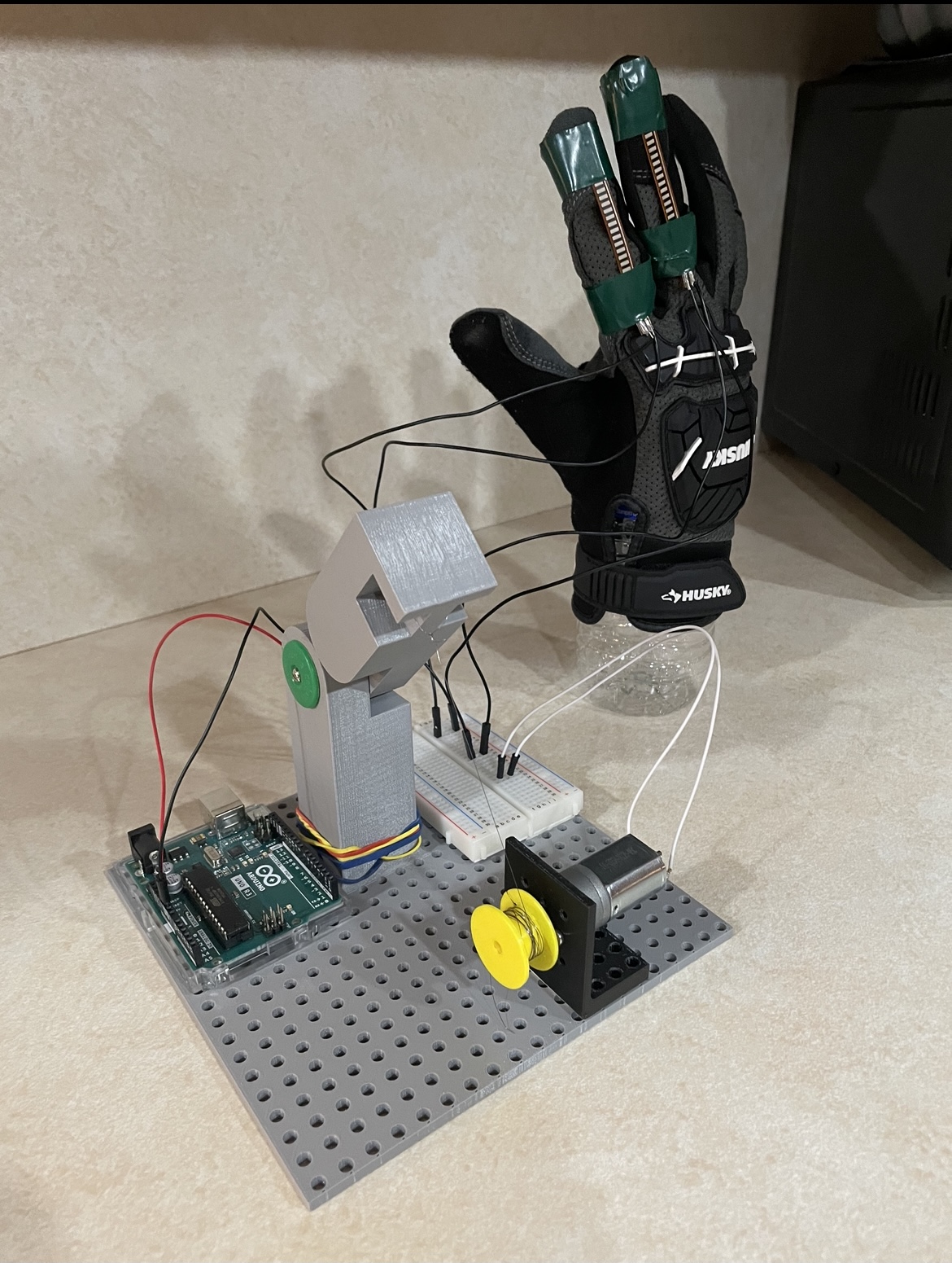
Prototype Features
- Input resistance from flex sensors
- Converted voltage from voltage divider
- 12V motor driven by current “bend angle” of data glove
Up next
- Encoders to implement angular position control
Proof of Concept
- Provides proof that our pinned joint design is effective when operated by a cable
- Proves that torsional bands are enough to pull the join straight when load is released
Current Arduino Logic
const int flexPin = A0; // Pin connected to voltage divider output
int motorPin = 2;
const float Arduino_voltage = 5; // voltage at Ardunio 5V line
const float Resistor_value = 47000.0; // resistor used to create a voltage divider
const float Flat_resistance = 34000; // resistance when flat
const float Bent_resistance = 54000; // resistance at 90 deg
void setup() {
Serial.begin(9600);
pinMode(flexPin, INPUT);
pinMode(motorPin, OUTPUT);
}
void loop() {
int ADCflex = analogRead(flexPin);
float Voltage_flex = ADCflex * Arduino_voltage / 1023.0;
float Resistance_flex = Resistor_value * (Arduino_voltage / Voltage_flex – 1.0);
Serial.println(“Resistance: ” + String(Resistance_flex) + ” ohms”);
// Use the calculated resistance to estimate the sensor’s bend angle:
float angle = map(Resistance_flex, Flat_resistance, Bent_resistance, 0, 90.0);
Serial.println(“Bend: ” + String(angle) + ” degrees”);
Serial.println();
//digitalWrite(motorPin, HIGH);
if (angle > 90) {
digitalWrite(motorPin,HIGH); }
else {
digitalWrite(motorPin,0);
}
delay(500);
}