High Level Design
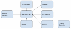
As specified in the figure below, sensors will be wired across two MCU’s. The first MCU is the Arduino Nano RP2040 which will control the functionality of the system as well as Wifi connectivity. The second MCU will be to interface with the charge controller and transmit the relevant data to the other Arduino. In regards to the sensor wiring we have three I2C sensors that will share the same bus, as well as four pins dedicated to the motors and four pins dedicated to the solar tracking. Figure below additionally shows the data flow.
High Level Overview of Digital Design
I2C
In our proposed design we are planning to use several Arduino boards notably ESP32 and Nano RP2040 Connect. In order to communicate between these devices we will be using I2C to allow for connections to multiple devices. We have tested the communication between Arduinos using I2C and found that it is highly reliable, as well as when it is using I2C and analog sensors. One of the limitations of I2C is the distance that it can cover reliably is typically a few meters which is not an issue in this case as the Arduino’s will be significantly closer than that. Currently, the Nano RP2040 Connect is the master that is controlling the ESP32 as well as all I2C sensors.
Arduino Carrier Board
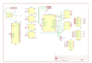
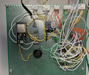
The image below is the schematic for the Arduino board implemented on the perf board shown below as well. This board contains both MCU’s, the protection circuit for H-bridge outputs, FTDI converter, and all I2C sensors other than the two compasses.
Wire Harnessing
A wire harness will be a key component of our design. Given the number of sensors used in our design, proper cable management will be necessary to keep wires organized. Another major component of the wire harness is making sure wires stay secure. Our system will be mobile and that means wires will be shaking around. Secure connections are of the utmost importance. Connections will also be important when connecting sensors on the frame to the Arduino in the case. Making sure we have secure connections between these wires, as well as using a connector that the user will be able to easily attach and detach is important. The key components of the harness are detailed below.
One of the most important aspects of harnessing was picking correct wire gauges. For all of the sensor wiring we used 22 AWG wire. Given the low current demands, we picked a gauge that was small as well as supported by a wide range of connectors. For connecting the battery to the power board and Inverter we used 2×4 AWG wire, to deal with the high current demands. For motor connections we used 16 AWG wire, providing a nice middle ground between current demands and sizing.
For connectors we used a couple different options. For our sensor connectors we used a 2.5 mm pitch Molex(Pictured below). These connectors allowed for easy use with our boards and were very plug and play in nature. One of the important specialty connectors were the Squaba Sealed Connectors. These connectors were used as disconnects between the turret and base They provided relatively high current capacity (14A) as well as a waterproof connection.
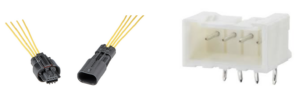
Squaba Wire-Wire Connections (left) and Molex Board Headers (right)
Sleeving we can use for cable management. Since we will have multiple wires going to almost every component it would be good if we could easily keep them together. Beyond that, sleeving should protect from heat and wear and tear, given the battery and especially inverter, could operate hot. We also will need sleeving, for the exterior wiring. While interior sleeving is more so for cable management, exterior sleeving will also need to protect from the elements. Insulated sleeving will be more infected from rain or other liquids that could potentially come in contact with the wire
Molex Connector Board Molex Connector Wire
For wire to board connectors, we have decided to go with Molex connectors. These connectors have 2.5 mm pitch, so they will be compatible with the spacing of arduino pins, as well as the pins on our power board. The Molex connectors come in sizes from 2 circuits to 15 circuits, allowing for some flexibility in terms of sizing and the amount of wires we will be sending through each sleeve.
For wire to wire connectors, we will be making use of two different types. One will be a weatherproof, buckle connector. These will be used for external sensor connections, as they will be exposed to the elements, and need to be attached and detached by the user while assembling and disassembling.
Sensors and actuator and motor wiring
The sensors that are used in the system are as follows:
- Adafruit Triple-axis Magnetometer – LIS3MDL Link: Used to know the orientation of the base.
- Temp/Humidity/Pressure (BME 280-Link): Used to monitor environmental data
- Photovoltaic sensor (HiLetgo 100pcs 5528 Light Dependent Resistor LDR 5MM Photoresistor Photoconductive Resistance-Link): Used to assist solar tracking
- Compass and Accelerometer (Adafruit LSM303AGR Accelerometer Magnetometer-Link): Used to know the orientation of the solar panels so that we can create an accurate solar path for the solar tracking
- Real Time Clock (Adafruit 3296 DS1307 Real Time Clock Breakout Board-Link): Used to keep track of time for the closed loop solar tracking path
- Interface with Renogy MPPT Charge Controller used to pull relevant information from the charge controller using an FTDI converter and manually stripping relevant data points Link
Here you can find datasheets for electrical design: Electrical Design Datatsheets
Here you can find all the code related to Arduino: Arduino Code
Arduino RP2040 Connect Datasheet
ESP32 Datasheet