Overview
The solar panel is made unique by its dual axis solar tracking mechanisms, which includes tracking using preset values according to the location of the panel and using light sensors to determine the direction of the sun.
Theory
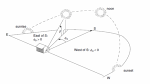
Illustration of solar angles
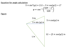
In order for the solar panel to always be perpendicular to the sun beams and generate maximum power, it would need to be able to make a total range of 240 degrees horizontally and 74 degrees vertically. This means that on the horizontal plane, and on an average day in the summer it will need to move from 60 degrees to 300 degrees, with the north being 0 degrees. On the vertical plane, the panel needs to be able to move from a position where it is perpendicular to the ground, at which the azimuth angle will be zero, until it goes to 74 degrees. Due to design constraints the minimum tilt angle was changed from 28 degrees to 33 degrees which gave us a theoretical energy loss of 1%.
Open Loop Sensor Design
Values of the different starting azimuth and altitude angles for each morning and every hourly change afterwards until dawn will be stored as an array, so the solar system can track or verify the sun’s position using pre-calculated values.
Closed Loop Sensor Design
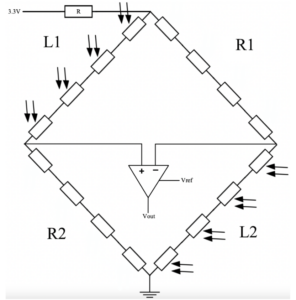
Wheatstone bridge for closed-loop solar tracking
The photoresistors will be placed in the four slots, so the accuracy will be adjustable as we either move them closer or further away from the center. Each photoresistor will aid in determining the direction in which to move the panel in order to track the sun. For that, a wheatstone bridge and an amplifier is used (see Figure 5). If the sun beam is not parallel to the wedges, they will cast a shadow on some of the photoresistors, therefore giving us a high resistance, so we will adjust the solar panel such that we have relatively similar values of resistance from each photoresistor.
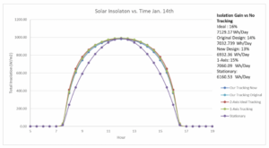
The analysis shown in figures below are based on Solar Time, Angles, and Irradiance Calculator. (Solar Time, Angles, and Irradiance Calculator – User Manual | New Mexico State University – BE BOLD. Shape the Future., n.d.). They demonstrate the ideal tracking capabilities for the solar tracker based on different yearly times.
See solar tracking schematics here: Solar Tracking
Hourly Power Generation vs. Time Jan 14th (Max Angle of 28.56)
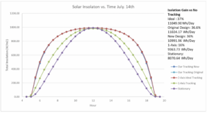
Hourly Power Generation vs. Time July 14th (Max Angle 71.67)
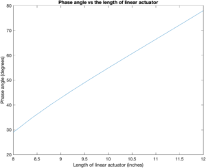
Angles that the linear actuator grants us:
Additional information: Solar Tracking Final Design