Propulsion Team Overview
End of Year Update
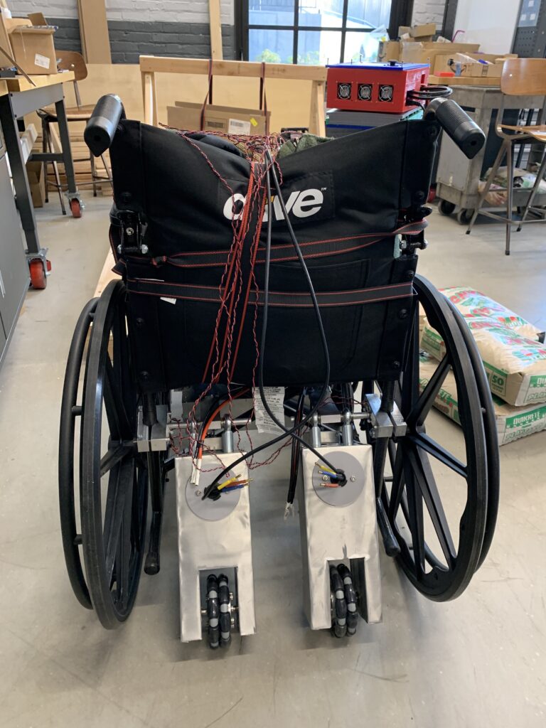
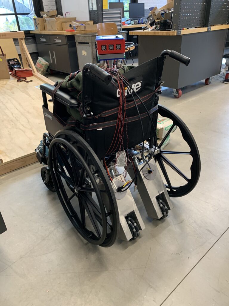
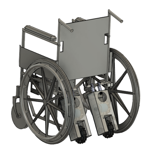
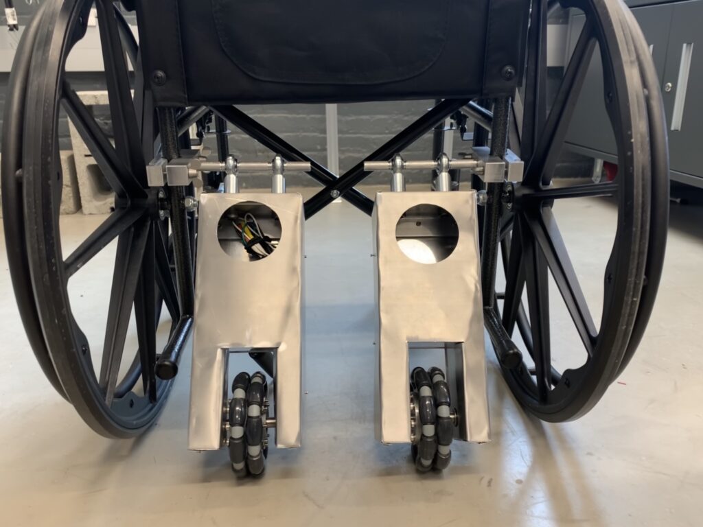
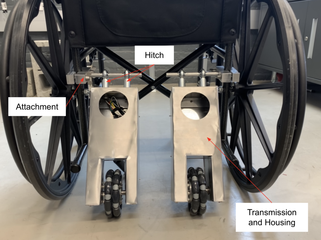
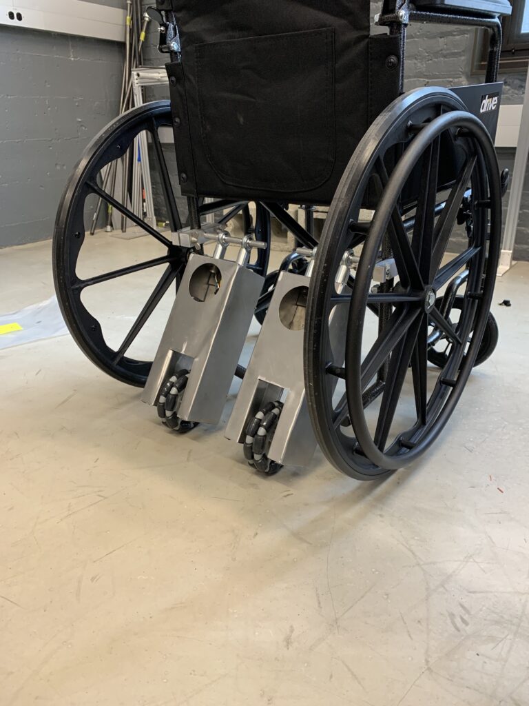
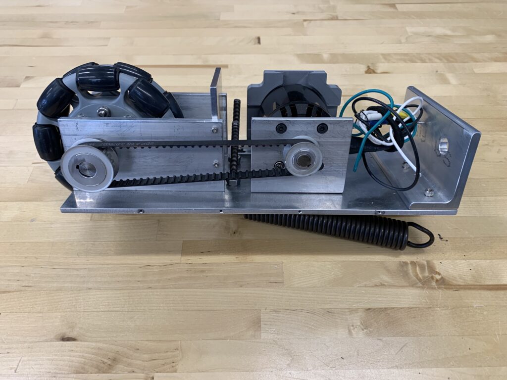
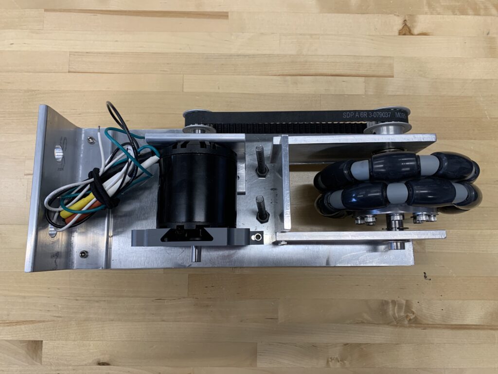
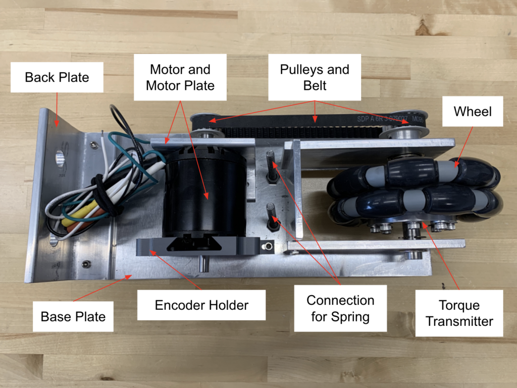
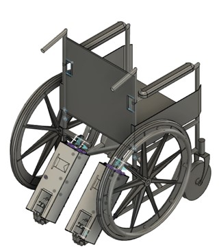
 Figure 5 Propulsion Team Current Prototype
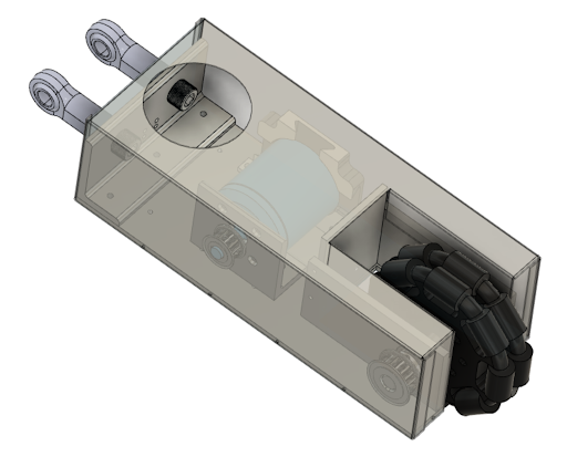
 Figure 6 Transmission and Housing
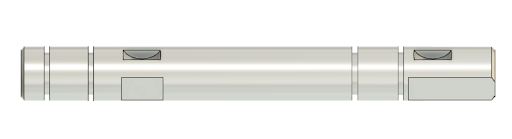
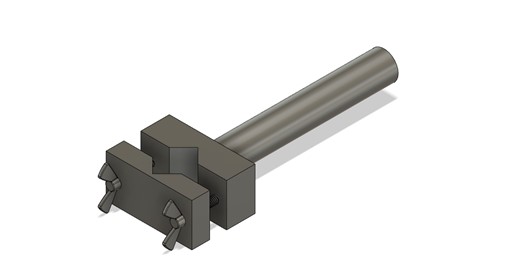
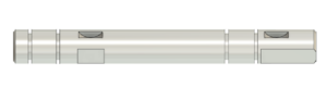 Figure 7 Drive Shaft
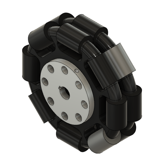
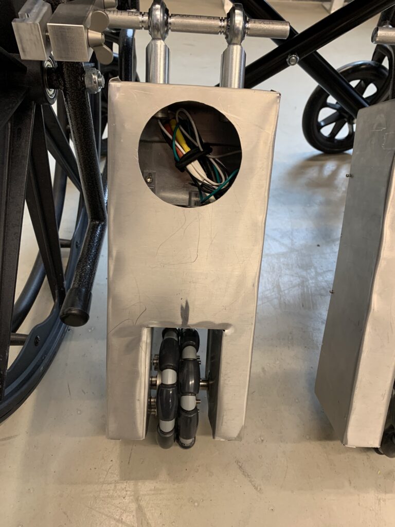
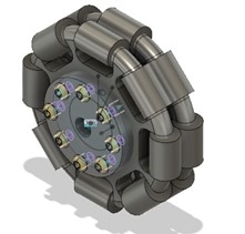
 Figure 8 Rotacaster Wheels and Torque Transmitter
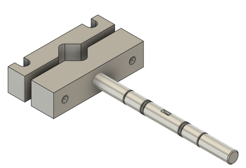
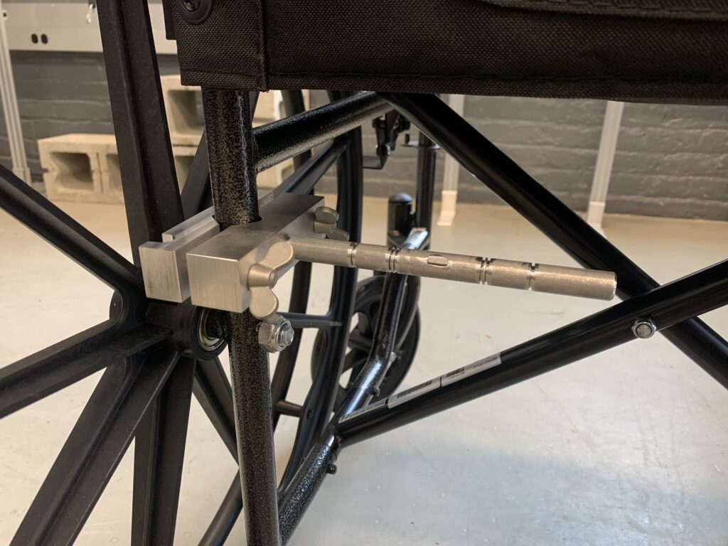
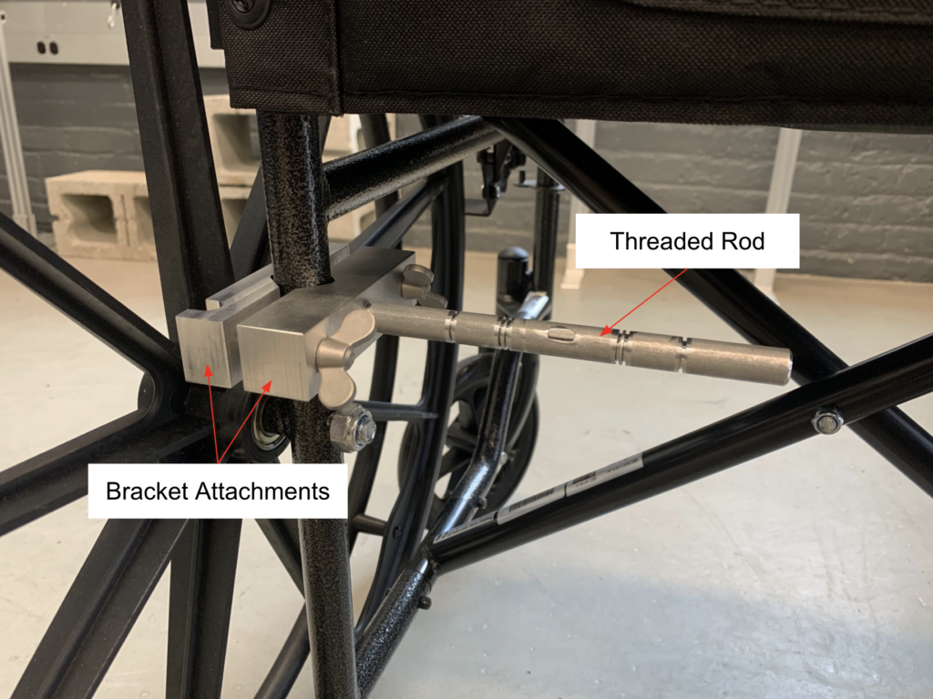
  Figure 9 Attachment mechanism that clamps to the frame of the wheelchair
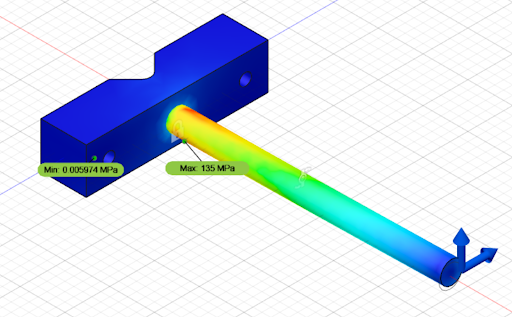
  Figure 10 Stress Analysis on the attachment rod
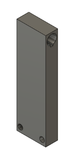
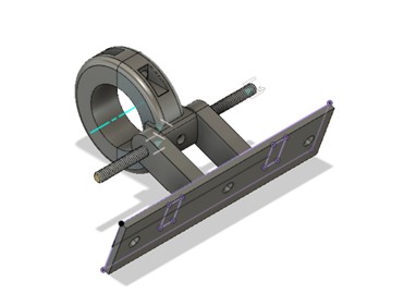
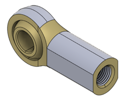 Figure 11 Connection between the transmission and housing and the attachment rod
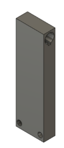 Figure 12 Spring Attachment Bar
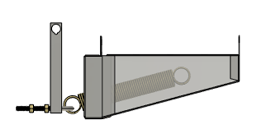
 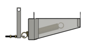 Figure 13 Spring Assembly including the spring, attachment bar and two part aluminum housing
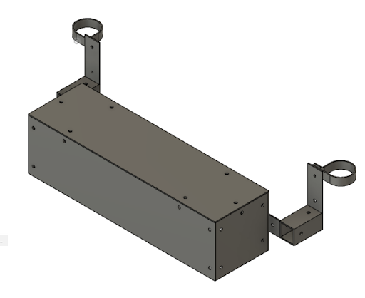
 Figure 14 Battery housing
Progress Update: Mid-March
Motor Test Run
End of the First Semester Designs
Conceptual Designs
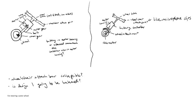 Figure 1 Propulsion system with belt driven wheel
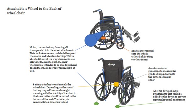 Figure 2(a) Propulsion system with singular wheel
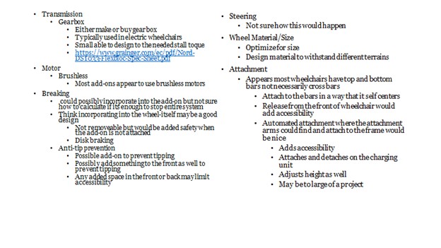 Figure 2(b) Propulsion system with one wheel possible configurations
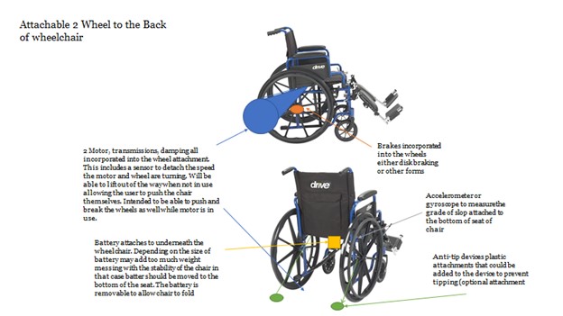 Figure 3(a) Propulsion system with two wheel
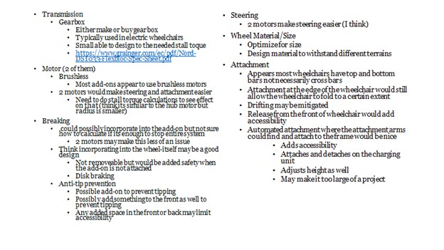 Figure 3(b) Propulsion system with two wheel possible configurations
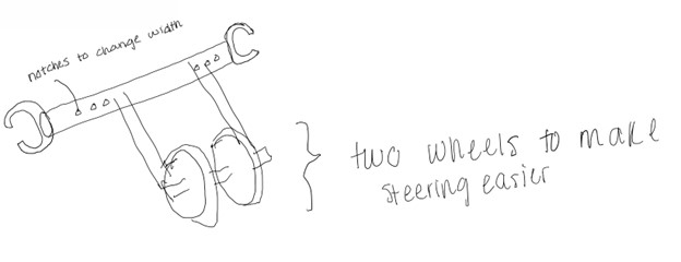 Figure 4 Propulsion system with two wheels
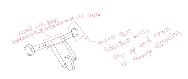 Figure 5 Propulsion system with one wheel
 Figure 6 Propulsion system attachments configuration
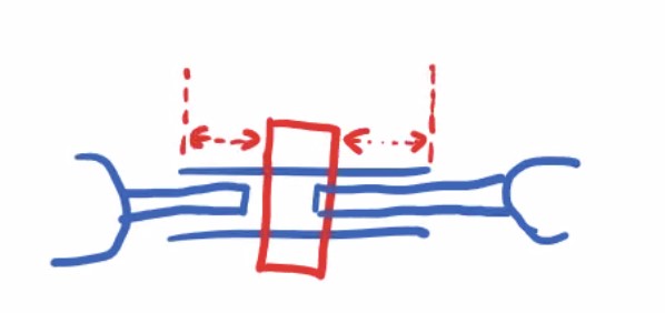 Figure 7 Propulsion system attachments configuration
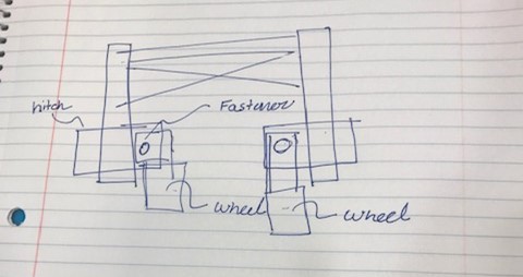 Figure 8 Propulsion system attachment and wheel configuration
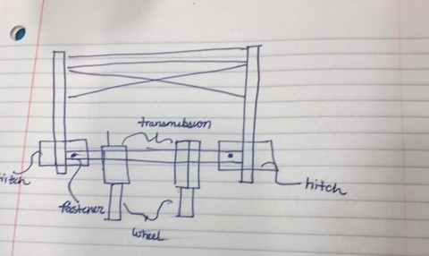 Figure 9 Propulsion system attachment, transmission, and wheel configuration
Calculations and FEA Analysis
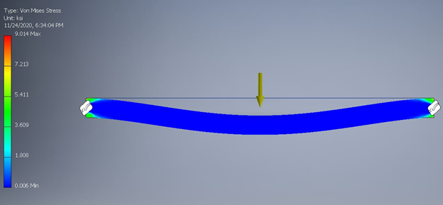 Figure B.14 ANSYS stress analysis for attachment full span shows maximum stress as 9.014 ksi
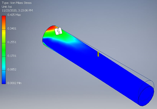 Figure B.15 ANSYS stress analysis for attachment partial span shows maximum stress as 0.425 ksi
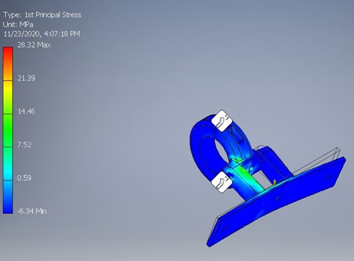 Figure B.16 ANSYS stress analysis for the hitch attachment shows maximum stress of 4.11 ksi
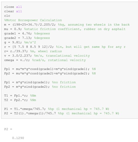 Figure B.17 Motor horsepower calculations in MATLAB
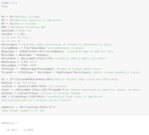 Figure B.18 Battery ampere hour calculations for chosen motor in MATLAB for running motor at 100% and 50%
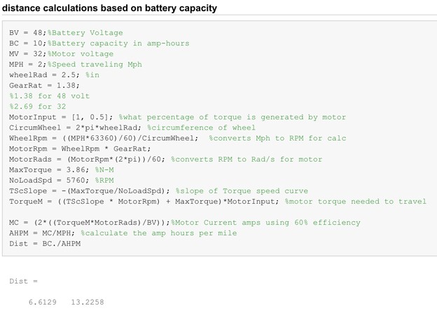 Figure B.19 Distance calculations based on battery capacity for chosen motor in MATLAB for running motor at 100% and 50%
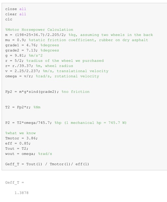 Figure B.20 Gear ratio calculations in MATLAB