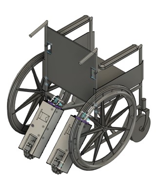
The propulsion team is faced with the design objectives of providing positive and negative torque, eliminating jerk, and allowing folding/interfacing with common wheelchairs. The propulsion team has decided on the placement of the device, the motor type, the battery type, the attaching mechanism, the transmission system, and the braking system. The team has also created CAD models of various components of the subsystem including the attachment to the wheelchair, the hitch attachment, the transmission, the transmission housing, and torque transmitters for the wheels. Designs for the braking system, battery housing, and lifting of the device when not in use are still in progress. The full design can be seen in Figure 5.
The propulsion team’s main metrics were the cost of the device, added weight of the device, range of the device, waterproofing housing for electric components, and maximum grade (Specification 1-5). The main constraint considerations for the propulsion system are maximum added width, maximum speed of a manual wheelchair and the maximum weight (Constraint 1-3). These specifications and constraints at times competed with the desired functions of the device. In deciding the placement of the device, the conceptual designs were narrowed down to designs that included systems attaching to the back of the wheelchair (Figures B.2 & B.8, See Images and Videos) and a system integrated entirely into the wheel of the wheelchair (Figures B.1, B.4, B.5, & B.6, See Images and Videos). The attachment to the back of the wheelchair would still allow the wheelchair to fold to some extent, it would be more likely to interface with different manual wheelchairs, and it would be an attachable and detachable device. The integration of the system into the wheels requires a choice: attaching hub motors to the wheels or creating new wheels for the wheelchair that would include hub motors. This design would allow the wheelchair to fold when not in use and to interface with many common wheelchairs as it would be a single installation process. The added width of the hub motors, however, was likely to violate Constraint 1, and the added weight of the hub motors was likely to violate Specification 2 because using two motors would add approximately 20 lbs of weight [27]. For these reasons, the add-on will be attached to the back of the wheelchair, and two motors will be used to allow for steering. This design does add concerns in regard to the functionality. In particular, the added weight to the back of the wheelchair will change the center of gravity of the wheelchair. There is a concern that because stability has not yet been analyzed, the added weight and shift in center of gravity may make the device more likely to flip when going down a hill. Additionally, the propulsion system will not interface directly with the wheels of the wheelchair, making braking and going down steep inclines more difficult as braking will be attached directly to the wheels instead of done by the motor and transmission. This complicates use of the device possibly limiting the spectrum of users.
The ODrive Dual Shaft Motor – D6374 has been chosen due to the motor horsepower calculations found in Appendix B. A motor with a minimum of ⅛ horsepower is needed to move the wheelchair at 3 mph on a 12% grade. 3 mph was derived from Specification 9 & 10, because it is within the range of 2.25 mph and 9.32 mph, and 12% grade (Specification 6). 3 mph is the average walking speed of an adult, so it provides safety and keeps the motor operating above the minimum velocity [19]. The calculations for determining a ⅛ horsepower motor can be seen in Images and Videos (Figure B.17). The ODrive Dual Shaft Motor -D6374 exceeds the need for ⅛ horsepower at 3.12 horsepower. The motor was chosen because it achieves the desired horsepower and was the least expensive of other fractional horsepower motors commercially available.
A 48V, 10 amp-hour battery must be used, as this was determined to provide enough energy capacity for this specific motor. To determine the capacity needed, a torque-speed curve was created from the max torque and no load speed of the motor provided by the manufacturer. This linear relationship between torque and speed allows for the torque required to go certain speeds to be determined. Using the torque required to go at a speed of roughly 3 mph, the current that each motor draws per second can be calculated by multiplying this torque by the motor’s speed in rad/sec then dividing this by the voltage of the battery. Using this, the distance needed to travel, and the travel speed, the battery capacity needed can be calculated. These calculations are shown in Images and Videos (Figure B.18). As determined by our calculations, which can be found in Images and Videos (Figure B.19), this battery will allow for the user to use the device at full speed for 6 miles, and at half speed, the device can be used for approximately 13 miles. This is consistent with Specification 3 and 4. Although the total capacity was calculated, these calculations were simplified as they do not take into account any friction and assume that the user is traveling along a flat surface. The estimation, therefore, for the capacity needed is a small underestimate of how much capacity is actually needed and these calculations would not work if the wheelchair was traveling up an incline.
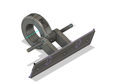
The component that will attach the device to the wheelchair can be seen in Figure 6. Having one attachment per side of the wheelchair will allow for the wheelchair to be partially folded. This is a design objective seen in Table 2. ANSYS analysis was done on bars that spanned the entire width of the wheelchair as well as only partially. This analysis can be seen in Images and Videos (Fig B.14 – B.15). The full span was constrained with two fixed supports on either end of the bar to simulate static loading (Fig B.14). The partial span was constrained by one fixed constraint on one side to simulate static loading (Fig B.15). The full span was loaded with a load of 300 lbs to simulate the possibility of this bar withstanding the full load of the device and user (Constraint 3). This was loaded only in the negative Z direction, or towards the ground, and in the center of the bar. This does not account for the placement of the attachments or direction of the loading the entire device would have and would have been updated accordingly, but this was only used for preliminary analysis in deciding attachment placement. The partial span was loaded with 40 lbs to overestimate the maximum weight of the device of 25 lbs maximum (Specification 2). This was placed in the center of the bar where the device will be placed and is only in the direction of the ground. Further analysis will correct issues with the constraints and placements of the loads to ensure they are aligned with the expected loads and directions of the device. The initial FEA was only used to ensure either the full span or partial span would be able to withstand loading. The maximum stress in full span attachment was 9.043 ksi and the maximum stress of the partial span was 0.425 ksi. Both analyses used aluminum because it is lightweight. Both configurations kept the stress of the material below the yield stress and the displacement of each was negligible. For this reason, a partial span was chosen to allow the wheelchair to be folded while the device is attached. The V-block configuration seen in Figure 6 will allow the attachment to interface with frames of different sizes. The wing nuts allow the attachment to be easily assembled and adjusted to different wheelchair frame diameters.
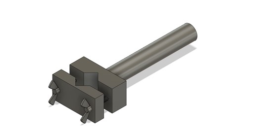
Figure 7 shows the hitch attachment. This attaches to the attachment above (Fig. 6) and allows for easy installation. The purpose of the hitch is to allow for freedom of movement along the axis of the attachment it is connected to. The component is made out of aluminum to decrease weight. ANSYS analysis was done on this component and can be seen in Images and Videos (Fig B.16). This shows the maximum stress as 4.11 ksi, which is below the yield stress of aluminum. The displacement of the component under loading is negligible as found through ANSYS analysis. The ANSYS analysis was loaded with one central load in the center of the plate that connects to the transmission housing in the direction of the ground. The analysis was loaded with a force of 40 lbs to be above the maximum weight set by Specification 2 of 25 lbs to ensure the device will not fail. This will need to be refined as further details of the weight and forces associated with the transmission housing are solidified to ensure that the direction and loads associated with the device are correct. The device was constrained with fixed supports on the attachment to the attachment to the wheelchair (Fig. 6) and pin connections in the pin between the circular member and the plate member. Further analysis will need to be done to ensure these calculations are correct.
A belt drive is being used for the transmission. The gear ratio for the belt drive was determined using the gear ratio calculation, which can be found in the Images and Videos Section (Figure B.20). From this code, a gear ratio of 1.3878 is needed to move a wheelchair with a person of 198 lbs 2.25 mph on a 12.5% grade (Specification 10). The housing for the transmission is shown in Figure 8. The base is made out of 3/16” aluminum and the cover is made out of 0.032” aluminum sheet metal. Because both components are made out of aluminum, this component is both lightweight and weather-resistant (Specification 2).
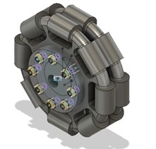
Rotacaster wheels were chosen and purchased as the wheels for the device shown in Figure 8 and Figure 9. They have rollers on the extremity allowing them to roll in multiple directions. This will decrease drag when the wheelchair is turning. Additionally, a part is needed to be created to transmit torque from the axle to the wheel. The current part is seen in Figure 9. It will interface with a current hole pattern from the purchased wheels. The holes will be tapped to allow for the bolts to attach to the wheels. A piece will press-fit into a natural depression in the wheel to increase the strength of the part. A set screw will be used to ensure the wheel is turning with the axle.
While not yet completely designed, the braking system will use caliper brakes from a bicycle. This will eventually accomplish Specification 12. Modifications will be made to allow brake handles typically used on bicycle brakes to be easily used and operated by wheelchair users that may have limited mobility or dexterity.
In order to allow for the user to use their wheelchair and not run the motor, a design to lift up the two attachments is being generated. While not completely designed, this system will include a ratcheting mechanism and cords. The purpose of this design is to prevent drag when the device is not in use.
The current design is still in development. It will continue to develop throughout the year as more research is done, communication with stakeholders occurs, and concepts are refined. The aim of the project is to develop a device to aid wheelchair users in going up and down inclines. To develop a design and actual device will be a continual process including brainstorming design objectives and conceptual designs as well as setting up constraints and specifications for the design. Ultimately, this will allow for a successful design and product that will enable wheelchair users to have more autonomy.