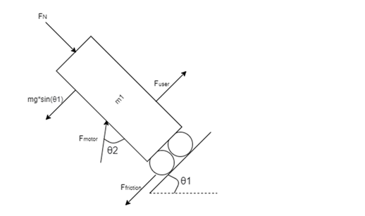
The goal of the effort sensing team is to determine the force applied by the user which is independent of all other forces on the chair. The current design is centered around a mathematical model approach. User input can be measured directly from the user or measured indirectly by measuring the overall acceleration of the chair and using a model to find the force needed to cause this acceleration. The latter was chosen because of simplicity and preventing unnecessarily added bulk relative to other approaches. New equipment would be needed to directly measure the force from the user. Equipment of this nature, such as torque sensors or added handles, could increase the footprint of the chair, making it less accessible, or cause it to be more difficult to use. Ultimately, the mathematical approach allows the team to find user input by measuring the dynamics of the entire chair rather than finding a way to measure one intermediate force with no interference (Figure 15). The main forces that have been identified include normal force, gravity, force from the user, friction, and the force of the motor. The diagram below models the wheelchair as a point mass and neglects all moments. This is the starting point because it simplifies the model as much as possible. If it is found later that the moments significantly affect the dynamics of the chair, the model can be reevaluated.
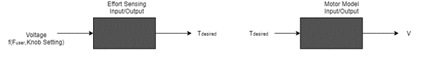
A systems based model (Figure 16) was used to identify inputs and outputs of the system. The input to the first block is a function of the forces mentioned above from the mathematical model and the user selected level of assistance. This block should then output the needed torque for the motor to supply. The second block will use the model of the motor to determine the voltage needed to meet this torque.
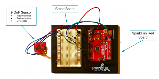
A 9 degree of freedom sensor (Figure 18) was selected to measure the necessary information to implement the mathematical model. This sensor includes a gyroscope, magnetometer, and accelerometer which are built into the chip. The advantage of this sensor over an accelerometer is it allows for calculation of angle with significantly less drift. The current prototype includes the 9 degree of freedom sensor, a bread board, and a RedBoard. The bread board and the RedBoard are only used for prototype testing and will not be used in the final prototype because the sensor will be integrated into the electro-mechanical subsystem.
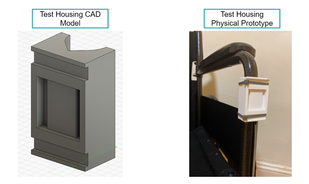
The current accomplishments include a physical prototype (Figure 18) from which data has been collected. Also, test housing (Figure 17) has been designed and 3D printed to aid in testing because it is essential the magnetometer be held in place to maximize accuracy of readings. This housing will not be used in the final prototype because the magnetometer will most likely be integrated into the electro-mechanical integration substeam’s housing.