Modifications to the current design would involve waterproofing the electrical components. We were able to waterproof the housing using a clear sealant spray, but the electronic components were not a priority. The wheelchair is ideally going to be in use in various weather conditions, so making sure the components are protected is important. Environmental conditions such as rain or snow can be an example of aspects that we want to protect against. There is a chance for water to seep through the holes where the LCD screen is, where the joystick is, and where the switch is. To prevent damage to these components as well as other electrical components inside of the interface housing box, we would want to get a protective covering for all the components. We have considered using epoxy, silicone, and fluoropolymer as waterproofing options.
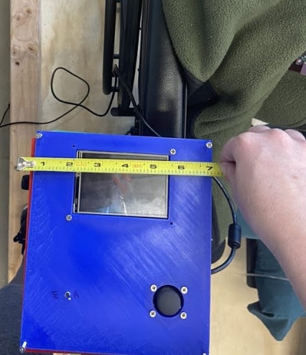
There could also be modifications to the housing, including the size and materials used. The interface housing box is about 6.5 inches wide by about 7 inches long, so trying to minimize this would be ideal. A measurement of the current box can be found in Figure 31. We could create shelves for the various electronic components to sit on so the box could be shortened in both length and width. The material can also be switched from 3D printed material to aluminum sheet metal. This may help with reducing the overall weight of the box, although it may increase costs. That is something that needs to be considered when designing and budgeting for the interface.
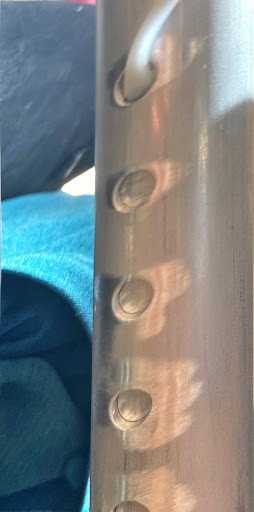
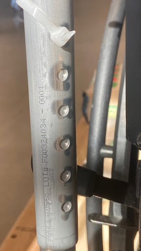
Furthermore, the spring rod attachment needs to be modified in the sense that the rods need to be re-drilled. The holes are not aligned directly across from each other, which has caused issues when trying to insert the pins into the system. We used zip-ties to secure the rods to the wheelchair and to the hinge, but this does not allow the spring-rod attachment to be adjustable. An image of this can be seen below in Figure 32. The user cannot raise or lower the interface, which was not ideal. By creating new holes in the rods, we could have the user adjust the height of the interface rather than only having it at one height.
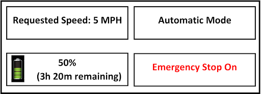
Another modification would be to the code, allowing the user to have a working LCD screen to see various aspects of the wheelchair add-on features and an indication of if the battery needs to be charged. The LCD would ideally show the user the battery level, the mode the user is in, the speed the user is going, and if the emergency stop button is activated or not. An example of this can be found in Figure 33. Having a working LCD screen will allow the user to to identify important aspects of the wheelchair add-ons and make them aware of important information. The noise to indicate that the battery level is low and needs to be charged is important so the user does not try to use the motors and they do not run. This will prevent frustration and allow the user to plan how they can use their wheelchair and if it will run how they want it to, when they want it to.
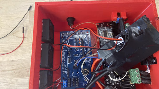
Finally, modification to the circuit board should be made as well. We did not include the voltage regulator on the final version of the customized circuit board, making use of a separate circuit board wrapped in tape for this, shown in Figure 34. For the next prototype development, a voltage regulator should be included to simplify the electrical components and wiring that is inside of the box. Simplifying the amount of wires and electrical components is desired and would be a simple modification in later versions.