The propulsion system overall performed well and a considerable amount of thought and design went into creating a successful first prototype. Despite the effort, there are improvements that would have improved the overall design and functionality of the device.
The main issue with the transmission and the transmission housing is that the design is flipped for the left and right housing, which was chosen because the design is not symmetrical. The wheel is not completely centered on the shaft, so to make sure we go straight, it was chosen to have the two different housings as mirrors of each other. This added extra difficulty for the EMI team when coding the motors because the two motors were different orientations. By making the design symmetrical, this would have cut out the extra difficulty added for coding the motors. Another issue with the design of the transmission, is the slots in the motor plate allowed for a tight fit for the belt on one of the transmission assemblies, but not as tight of one for the other. In another iteration, the slots would be designed to be larger to allow for more room to shift the motor forward and backward.
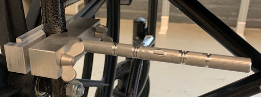
Installing the device is quite difficult for the user, which limits accessibility. To install the device themselves, the user would need to get out of the wheelchair. The attachment rods that link the transmission to the chair require tools to install in order to ensure that the grip is tight enough to fix the transmission housing to the wheelchair and prevent it from rotating around the tubing. Originally, wing nuts that could be tightened by hand were used instead of the bolts to attach the v-blocks to the wheelchair (Figure 29). Though this may have been easier for the user to install, it did not create a tight enough grip on the tubing to cause the transmission to push the wheelchair. A solution that would be easier for the user to install without tools without sacrificing the strength of the attachment grip would need to be developed.
Installation is also difficult currently because the spring has to be extended to be installed. This would most likely be difficult for many of the devices intended users as many might have limited mobility or upper body strength. For this reason, a redesign of the spring should be considered especially when considering multiple installations. A device that aids in the extension of the spring may be useful or a weaker spring may mitigate some of the difficulty. Additionally having the spring as an optional piece may be wanted by some users. This might be wanted because of the decrease of difficulty of installation and the ability to overcome obstacles of greater height than 6 inches. The spring allows the device to stop and go backwards on some declines/inclines but does not prevent the device from stopping or going backwards on all inclines. The device should maintain a normal force on level ground when going backwards and up to a 5% grade based on spring calculations. Further testing would show if these calculations were correct. Another solution would be to change the implementation of what creates the normal force. This might include leaf springs or other configurations of extension springs or torsion springs.
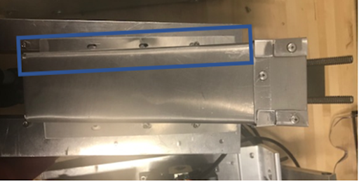
Using bent aluminum proved to be difficult to manufacture and make consistently. As shown in the figure below (Figure 30) there are some differences and alignment issues of using aluminum for the spring housing. This occurred because of the complexity of the sheet metal design and the size being quite small. While the aluminum makes the device consistent with the aluminum transmission housing and makes for a fairly weather resistant design, this inconsistency in housings is concerning. To improve this, it may prove to be more effective to 3D print the spring housings as they are a safety addition not a structural addition so they do not need the strength of the aluminum. Waterproofing 3D printed housing would keep the housings consistent and repeatable which would be great for manufacturing.
The torque transmitter works well but it could be improved. This could happen through better aligning the holes of the transmitter ensuring that they align with the holes of the wheel. The wheel works well but further testing might have shown that the wheel could not withstand the constant loading of the device. If this was shown to happen, manufacturing our own omni-directional wheel out of a stronger material could improve the overall performance.
The battery and the battery housing have complications with the design of the housing, and the chosen battery. The chosen battery is lithium ion, 48V, 10 amp-hour, and 5.2 lb. According to the Federal Aviation Administration, FAA, lithium ion batteries can be carried on a plane if they are under 100 watt hours [17]. Our battery is 480 watt hours, which means the current battery cannot be carried onto an airplane. In order to fix this problem, a method of hot swapping could be used with smaller amp-hour batteries. By using five 48V, 2 amp-hour batteries, the batteries would be allowed on a plane, and still allow for the same desired range, 1.5 miles with no user assistance (Specification P1). There were difficulties with finding a way to clamp the housing to the frame of the wheelchair. Currently, it swings when the wheelchair is moving. If given more time, a new clamping mechanism would have been designed. The current housing also has a side that is not secured to any other side, which means it opens similar to a door. While this does allow for the battery to easily be removed from the housing, it could prove problematic if the battery moves too much. If given more time, a mechanism to secure this, while also allowing for the battery to easily be removed would also be designed.
The weight of the propulsion system is quite heavy. Weighing 26.8 lbs total exceeds Specification G2 putting a limit at 25 lbs of additional weight. To cut down on weight the spring attachment bar may be made out of different lighter material or some of the bar be cut out because it is currently a solid block of aluminum which is quite heavy. The use of different materials may generally cut down on weight and the use of plastic for non structural pieces such as the housings may cut down on some of the weight of the device. Also, by making the adjustment described above about the battery, the weight of the battery can significantly be reduced, which will reduce the overall weight of the propulsion assembly.