Goal of Test
The goal of the static stability test is to ensure stability of the wheelchair with the add-on on a ramp under varying inclination conditions. This test procedure is given by ISO standard 7176-1 referring to Specification P3 [Section 4] [14]. This test will test for Specification G5 and P12 [Section 4].
Procedure
- Prepare ramp for testing by positioning the ramp to the lowest angle using the car jack.
- Place the wheelchair on the test ramp. The test should be repeated 3 times for a forward (Figure 24a), backward (Figure 24b) and lateral orientation (Figure 24c). The following diagrams depict the orientation for the three different orientations
- Place the roll restraints in front of the wheels located closest to the bottom of the ramp.
- Position dummy in wheelchair at specified location according to center of mass positioning requirements.
- Secure the test dummy using ratchet straps to the rail of test ramp to secure wheelchair in case of tipping
- Increase the angle of the platform by cranking the car jack until wheelchair tips. Record this angle to the nearest degree.
- Lower the test platform using the crank on the car jack until it is in its lowest position.
- Repeat steps 2-7 to ensure the wheelchair and add-on are tested with the three different orientations. Reference Figures 1a, 1b, and 1c
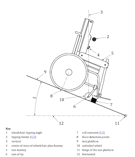
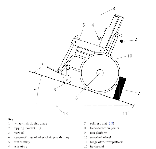
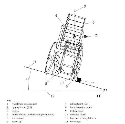
Figure 24. ISO diagrams for three different wheelchair positionings [2].
Required Equipment
- Adjustable Ramp
- Car jack and mating attachment for raising and lowering the ramp
- Ramp
- Test Dummy (eg. a bag of sand)
- Ratchet Straps
- Roll Restraints
- Roll restraint surfaces that contact a wheel shall be perpendicular to the test plane. The height of the roll restraint shall be sufficiently large to prevent rolling of the wheels during testing
- For specific orientations, reference Figures 1a, 1b, and 1c.
- Sandbags were used as roll restraints
- Angle Measurement Device
- Tape measure and trigonometry was used to determine the angle
Safety
We were concerned with the instability of the roll restraints. However, the sandbags worked well to restrain the wheelchair. Clearing the area surrounding the ramp was important for bystander safety. We wanted to ensure that no one gets injured by the wheelchair or any of the setup. We only had experienced individuals touching the equipment and kept bystanders away during testing. The trained individuals remained at the top of the ramp before and during the test.
Results
The results of the static stability test showed that the addition of the device did not pose a threat to the static stability of the wheelchair. As shown in Table 7 the angle at which the wheelchair would tip with the device attached is greater than 17.58° for all orientations. This occurred because the wheelchair did not tip in any orientation at the maximum angle the adjustable ramp can achieve. An angle of 17.58° is a very large incline especially for a roadway and is not expected to be found regularly. This can be seen in the figures below of the different orientations of the wheelchair at the maximum angle of the ramp. 17.58° is 31.7% grade which is larger than the safely transferable grade incline of 8.5% specified in Specification P3. This means that the device should not pose an additional risk of tipping in the majority of uses.
Table 7 Results of the Static Stability Test
| Orientation | Angle (deg) |
| Forward | > 17.58 |
| Backward | > 17.58 |
| Lateral | > 17.58 |
Required Equipment
- Adjustable Ramp
- Car jack and mating attachment for raising and lowering the ramp
- Ramp
- Test Dummy (eg. a bag of sand)
- Ratchet Straps
- Roll Restraints
- Roll restraint surfaces that contact a wheel shall be perpendicular to the test plane. The height of the roll restraint shall be sufficiently large to prevent rolling of the wheels during testing
- For specific orientations, reference Figures 1a, 1b, and 1c.
- Sandbags were used as roll restraints
- Angle Measurement Device
- Tape measure and trigonometry was used to determine the angle
Safety
We were concerned with the instability of the roll restraints. However, the sandbags worked well to restrain the wheelchair. Clearing the area surrounding the ramp was important for bystander safety. We wanted to ensure that no one gets injured by the wheelchair or any of the setup. We only had experienced individuals touching the equipment and kept bystanders away during testing. The trained individuals remained at the top of the ramp before and during the test.
Results
The results of the static stability test showed that the addition of the device did not pose a threat to the static stability of the wheelchair. As shown in Table 7 the angle at which the wheelchair would tip with the device attached is greater than 17.58° for all orientations. This occurred because the wheelchair did not tip in any orientation at the maximum angle the adjustable ramp can achieve. An angle of 17.58° is a very large incline especially for a roadway and is not expected to be found regularly. This can be seen in the figures below of the different orientations of the wheelchair at the maximum angle of the ramp. 17.58° is 31.7% grade which is larger than the safely transferable grade incline of 8.5% specified in Specification P3. This means that the device should not pose an additional risk of tipping in the majority of uses.
Table 7 Results of the Static Stability Test
| Orientation | Angle (deg) |
| Forward | > 17.58 |
| Backward | > 17.58 |
| Lateral | > 17.58z |
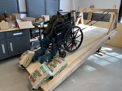
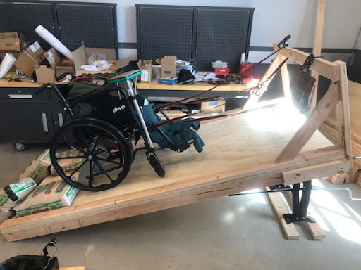
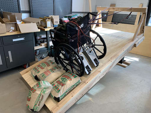
Figure 25a 25b &25c Static Stability test at maximum angle in the backwards (a), forwards (b) and lateral (c) orientations