The effort sensing subteam was tasked with goals relating to sensor measurement and the usage of those measurements in determining unknown forces. The three main goals included: modeling the linear acceleration and velocity profiles of the chair, determining the angle of the chair to be used in modeling gravitational forces, and measuring the force applied to the chair from the propulsion system.
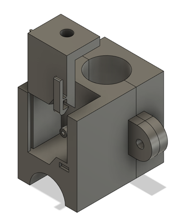
The first two design goals were planned to be accomplished using a nine degree of freedom, or 9DoF sensor. This type of sensor is capable of sensor fusion of an accelerometer, a gyroscope, and a magnetometer which in combination model the three dimensional orientation of an object. Originally the intention was to place this sensor in the control module for the chair with the rest of the electronics, but this placement was not adequate for several reasons. The control module is designed to move freely which means the relative orientation of the sensor and the chair would not be fixed, and this would be difficult to account for. Additionally, the magnomemeter component of the 9DoF sensor is highly sensitive to changes in magnetic fields and this close proximity to other electronics could skew the data. To solve this problem a separate mount was designed to hold the sensor away from other possible sources of magnetic fields which would also be very stable. This mounting component, shown in figure17, was designed to be something that could be easily 3D printed while maintaining an easily latching cover so that the sensor could easily be accessed in this prototyping phase. Additionally, this component was designed so that it could be attached to the intersection of two pipes in the lower rear of the chair so that it could be clamped down in place, restricting motion in all directions.
This sensor seemed ideal for measuring angle as well as linear acceleration, but there were several unforeseen problems. This type of sensor is commonly used to determine orientation in space, and as such worked beautifully to measure the orientation angle of the chair while at rest. However, when any sort of linear motion was introduced the error in the measurement increases. This error was somewhat proportional to the magnitude of linear motion, but all attempts at error mitigation under the current time constraints have proved unsuccessful. The angle data from the sensor is not completely useless, but it has its limitations within this application. The effects of gravity on the chair can still be modeled and the propulsion system can be called accordingly to make hills feel more flat. The confidence in this system just decreases when any motion occurs which can be accounted for by having the system underestimate the needed force if motion is detected. This will prevent the system from becoming unstable with motion causing more error, causing more motion and so on, but it does mean that this assistance mode will be less effective than anticipated.
While the angle measurement data could still be used, the linear acceleration and derived velocity could not be used. At first glance the data appears to be accurate. When a sudden push was applied to the chair a peak would appear in the acceleration reading which slowly damped out. However, when deriving the velocity, using a high pass filter to eliminate drift, it became much more clear that the data being collected was not accurate. When the chair began to slow down the measured velocity would start to go negative and overshoot back into positive values for several seconds even after the chair had stopped moving. Consisting of only a single energy storing element in the form of its own mass, the chair should be a first order, and visually appeared to be the case, but the 9DoF sensor was producing a plot which looked to be a heavily damped second order system. To make matters worse, if the chair happened to hit even a small bump the data would briefly become unstable and completely unusable. Despite numerous attempts to determine a solution, including increased filtering, a complete rewire, and several different coding approaches, no suitable solutions were found. At this time it has been deemed unreasonable to use a measurement of linear motion to model the interactions of the user with the chair as originally planned. However, in making improvements on this design in the future it would be desirable to further research this system and possible other sensors that could be used.
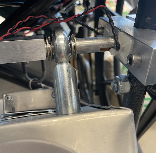
To complete the third design goal of measuring the applied force from the propulsion system, the effort sensing team decided to design a custom force measurement system using strain gauges. There were two strain gauges per rod aligned in a type II half bridge configuration used to isolate the bending strain in the rod caused by the propulsive force. Flats were milled into the propulsive rods to allow the gauges to attach fully to the bar. Similarly, strain relief was incorporated with zip tie attachments seen in the figure below.
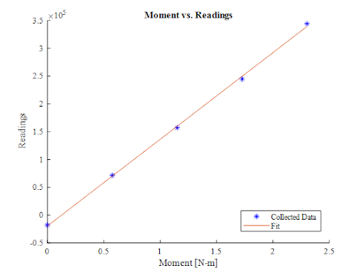
An amplifier board was used to amplify the gain of the readings from the sensor and allow for processing the data. The strain gauges were calibrated using a variety of weights from approximately 0 to 7 kg. The larger threshold was tested because it was slightly larger than the maximum propulsive force of approximately 60 N. Raw readings from the sensors were collected and fitted versus mass in MATLAB to determine if the correlation was linear. Because the correlation was linear and the masses were hung on the rod at a known distance from the fixed end, a moment versus raw readings from the sensor were also calculated from the collected data. This allowed for calculation of the propulsive force. The distance of the force applied by the propulsive add-on was assumed to be approximately the distance from the fixed end to the middle of the rod.
Initially, the strain gauges were designed to be attached to the direct top and bottom of the rod; however, this didn’t happen due to threading issues and the strain gauges were positioned at an angle of approximately 46 degrees off from the initially desired position. To account for this, the strain gauges were secured at this angle during testing to account for this change in angle. By doing this and experimentally determining that the change in strain gauge measurement was proportional to the angle at which the gauges were configured, both the right and left sides of the strain gauges were properly calibrated to correctly calculate the propulsive force.
In the end, the left side sub assembly had some issues and ended up breaking during integration with the full prototype assembly; however, the assembly works on the right side and theoretically could be used and just multiplied by two assuming the propulsive force on both is the same. Because of the limitations and challenges in integrating and using the 9DOF system, a full effort sensing code was never implemented, but ultimately the propulsive force was isolated.
The goal once the propulsive force and angle had been accurately isolated and calculated was to use each to power the motors as a function of those values. The angle measurement from the 9DoF sensor was used to calculate the force that would be needed to overcome gravity on an incline. Knowing the propulsive force from the strain gauge system, we could use a proportional controller coupled with overcoming gravity to provide a proper response to the user.