The electro-mechanical integration team’s focus was connecting the effort sensing and propulsion subteams to control the chair and create a user interface capable of controlling the system. The electro-mechanical integration subteam was responsible for creating an arduino script to control the logic of the chair, to integrate the propulsion and effort sensing subsystems into the main script in order for all parts to communicate, and to create a controller that could control the direction of motion and the mode of the chair.
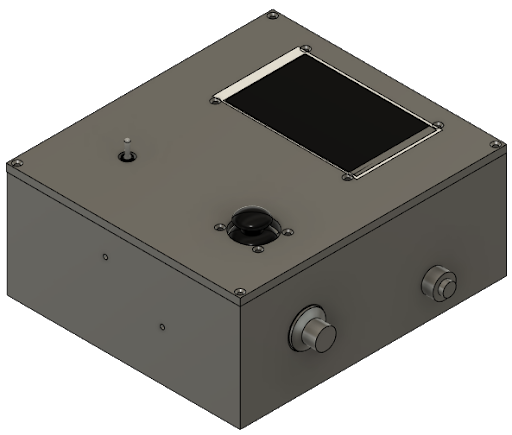
The controller was created to set the max speed of the chair, to control the direction of the motion of the chair and the speed at which it travels in that direction, to set the mode of the chair to effort-sensing mode, all assistance mode, or waiting mode, to house the emergency stop button, and to output information about the chair such as battery level, speed, and mode on the LCD screen. Additionally, the controller intended to create a beeping sound to notify the user of different circumstances such as low battery, reversing in the chair, etc.
The speed was intended to be set using the potentiometer. The max setting on the potentiometer would be the max speed allowable by safety standards and the user could set the max velocity of the speed of the chair at any given time using the potentiometer’s linear scaling. This final version of this concept has one revision from the intended design. Instead of the max setting of the potentiometer being determined by safety standards, the max setting is determined by the max input speed of the motor without causing an error, which was significantly lower than the safety guidelines. During testing, any voltage input to the motor greater than 5V caused an overload to one of the motors, disabling it until the code was reuploaded.
The joystick was intended to act as the way for the user to dynamically control the direction of the chair and the speed in that direction relative to the max speed set by the potentiometer. The farther the joystick was pushed from the center, the faster the chair would move, scaling linearly from motionless to the max speed. The arduino would perform calculations to determine how the chair would respond given how far the joystick was pushed in the horizontal and vertical directions and determine the motion based off of that. In the final design, the joystick acts as a purely directional controller, essentially allowing the chair to travel straight forwards and backwards and rotate clockwise and counter-clockwise. This change was made due to noise found in the reading of the joystick inputs that would spike and create issues with the motors while the joystick was in resting position.
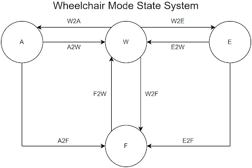
The mode switch was the intended method of changing between the chair’s modes. The chair was designed to have 4 modes: effort-sensing, full assistance, waiting, and fault. In effort sensing, the chair would make full use of the effort sensing subsystem to calculate the power and torque output by the motors to assist the user as desired. The potentiometer would set the effort level and the joystick would not be active. In the all assistance mode, the potentiometer and joystick would act as described earlier in this section. The waiting mode was intended to be the mode in which the chair would default upon start-up and the mode in which the motors would calibrate. Additionally, waiting mode acted as the intermediate mode during every mode transition. The final mode was fault, which acted as a fail-safe mode. The fault mode would be activated by depressing the emergency stop button and would cause the motors to stop the chair’s movement. This mode can only transition to the waiting mode and to do so the switch must be set to waiting and the emergency stop button must be unpressed. The switch is a three-point toggle switch with all assistance, effort-sensing, and waiting modes designated to each position of the switch.
The LCD screen was intended to display information about the chair such as battery level, chair speed, and effort level. Due to time constraints, the LCD board will be inactive. The buzzer will also be inactive within the housing due to the same time constraints. In addition to the components described above, the controller housing also contains the arduino mega board that controls the logic of the chair, the motor driver that acts as a medium through which the arduino communicates with the motors, the custom PCB circuit board used to connect the components to the arduino, fans acting as the system’s cooling mechanism, and a voltage regulator for the fans and arduino.
In addition to the electrical components used to control the chair’s motion, the electro-mechanical integration team created an adjustable mechanism to attach the controller to the chair. This mechanism is the combination of four concepts: adjustable interlocking hollow beams, a pin system to lock the sliding beams in place, a hinge for accessibility, and clamps to attach the beams to the chair. The sliding beams consisted of one beam in which the other two beams would slide into. These beams would have a spring inside to assist in adjusting the positioning of the beams. The pin system would act as the way to lock the beams into place. The initial design for this mechanism involved a small spring and rods that would compress the spring and allow the beams to slide. Through difficulties 3D printing the small rods, this rod system was replaced in the final design with a simple pin and key system in which a pin would be inserted through the beam holes to lock the beams into place and a smaller rod would be inserted into the pin to lock the pin in place. The hinge would attach to the top of the uppermost beam and would act as the mounting mechanism for the housing and allow the user to angle the screen and controls for comfort. The initial design of the clamps involved circular cups that would perfectly conform to the beams. Inspiration for the final design of the clamp came from the clamp design used in the propulsion team’s motor attachment mechanism. The final design includes v groove clamps with wing head screws and barrel nuts to bind the clamps together.