The propulsion team is faced with the design objectives of providing positive and negative torque, eliminating jerk, allowing folding and interfacing with common wheelchairs. The propulsion team has decided on the placement of the device, the motor type, the battery type, the attaching mechanism, the transmission system, and the braking system. The team has created detailed CAD models and manufactured all the components of the subsystem, which will be described in detail below. The full design can be seen in Figure 5.
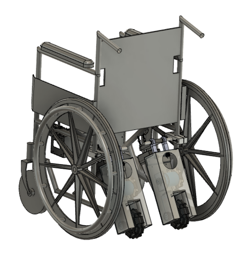
The propulsion team’s main metrics were the cost of the device, added weight of the device, range of the device, waterproofing housing for electric components, overcoming obstacles, and maximum grade. The main constraint considerations for the propulsion system are maximum added width, maximum speed of a manual wheelchair, and the maximum weight. These specifications and constraints at times competed with the desired functions of the device. In deciding the placement of the device, the conceptual designs were narrowed down to designs that included systems attaching to the back of the wheelchair and a system integrated entirely into the wheels of the wheelchair. Adding a device to the existing wheels would add extra width to the wheelchair, which makes it difficult for wheelchair users to go through tight spaces including doorways. The attachment to the back of the wheelchair would still allow the wheelchair to fold to some extent, there would be little to no added width, it would be more likely to interface with different manual wheelchairs, and it would be an attachable and detachable device, thus we decided the add-on will be attached to the back of the wheelchair, and two motors will be used to allow for steering.
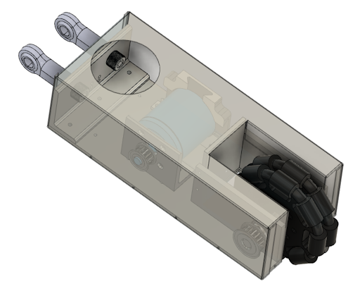
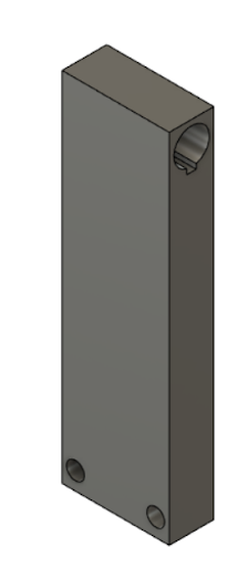
Figure 6 shows the CAD model for the current prototype of the transmission and the transmission housing for the propulsion team. This system is made up of many components: base plate, sheet metal housing, back plate, vertical plate, two shaft supporting walls, shaft with e-clips, flats, and a woodruff key slot, ODrive Dual Shaft Motor – D6374, motor plate, encoder holder, two pulleys, and a belt. Because there are two of these to allow for steering, the right side is a mirror image of the left side, but they both contain the exact same components.
The base is made from 0.190” aluminum, and the housing cover is made from 0.032” aluminum sheet metal. Aluminum was chosen because it is both lightweight and weather-resistant (Specification G2, G3). The housing has a hole on the top because the threaded ball joints, which connect the housing to the rod that is attached to the wheelchair, are installed after the housing is secured to the base. This hole allows for these to be installed and tightened. These holes are filled with 3D printed parts and an expandable grommet, which act as a plug, to ensure no debris gets into the housing.
The ODrive Dual Shaft Motor – D6374 has been chosen due to the motor horsepower calculations found in Appendix B. A motor with a minimum of ⅛ horsepower is needed to move the wheelchair at 3 mph on a 12% grade. 3 mph was chosen because it is the average walking speed of an adult, so it provides safety and keeps the motor operating above the minimum velocity [8]. The ODrive Dual Shaft Motor – D6374 exceeds the need for ⅛ horsepower at 3.12 horsepower. The motor was chosen because it achieves the desired horsepower and was the least expensive of other motors in a similar horsepower range commercially available.
To support the motor, a motor plate was manufactured out of an aluminum 90 degree angle, and an encoder holder was 3D printed. The motor plate is used to support the motor and secure it to the base plate. The encoder holder is used to hold the encoder to the rear shaft of the motor, which is used by the EMI team to know the speed of the motor. Previously, the motor was placed in an entire housing whose design was provided by the creators of ODrive. This approach was abandoned because having a plate in the front and a holder in the back means the body of the motor is not enclosed, thus the motor is less likely to overheat. The motor plate has slots for where it is secured to the base plate. This allows for the motor to slightly shift in order for the tightness of the belt to be adjusted.
A belt drive is being used for the transmission. The gear ratio for the belt drive was determined using the gear ratio calculation, which can be found in Appendix B (Figure B.17). From this code, a gear ratio of 1.39 is needed to move a wheelchair with a person of 198 lbs 2.25 mph on a 12.5% grade (Specification P3). To achieve this gear ratio, pulleys with 14 teeth, and 20 teeth were chosen for the shaft of the motor and the shaft that holds the wheel respectively. As a result, the gear ratio is 1.43, which is slightly higher than the calculated gear ratio needed to move the wheelchair 3 mph on a 12% grade. This is okay because the device will be able to move the wheelchair slightly faster than 3 mph on 12% grade, but this small difference will not push it past the allowable speed of 9.32 mph specified by ISO standards.
Using the same material as the motor plate, the back plate was manufactured using an aluminum 90 degree angle. The back plate’s purpose is to transfer the force from the wheel to the attachment and to provide stability. On an earlier iteration, there was no back plate, which would have meant the only piece transferring the force from the wheel on the ground to the attachment bar would have been the sheet metal housing. This would have been a high amount of force on a thin piece of metal and would have most likely failed.
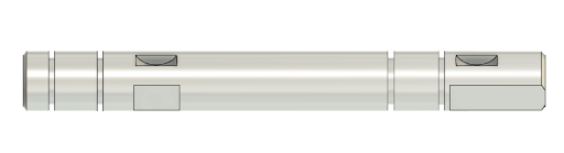
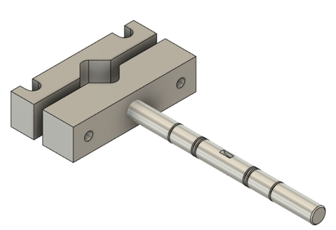
A stainless-steel drive shaft has been designed to hold the 20 teeth pulley, the wheel, and the torque transmitter, and CAD model can be seen in Figure 7. The shaft is stainless steel because it needs to be a higher strength metal, while also being able to withstand various weather conditions. The drive shaft is supported by two walls with ball bearings. It has grooves for e-clips to keep the shaft in the correct spot, a woodruff key slot for the pulley, and flats were milled for both the pulley and the wheel. A flat and a woodruff key were chosen for the pulley to ensure the maximum torque produced by the wheel would be able to be transferred from the wheel to the pulley.
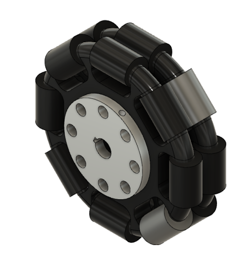
Rotacaster wheels were chosen and purchased as the wheels for the device shown in Figure 6 and Figure 8. They have rollers on the extremity allowing them to roll in multiple directions. This will decrease drag when the wheelchair is turning. Additionally, a part is needed to be created to transmit torque from the axle to the wheel. The current part is seen in Figure 8. It interfaces with a current hole pattern from the purchased wheels which have been modified to be thru holes instead of partial depth holes. Bolts go through both parts of the wheels and are secured using nuts on the other side. A bushing was press-fit into a natural depression in the wheel to ensure the wheel has a tight enough fit with the shaft. A set screw was used to ensure the wheel is turning with the axle. The torque transmitter and wheel currently fit well based on turning the wheel and motor with no slip between the wheel and driveshaft.
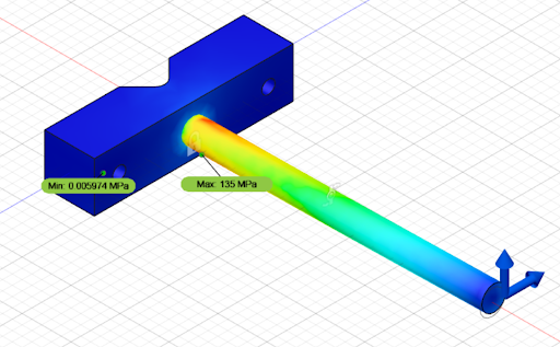
The transmission and housing are attached to the wheelchair using the attachment bar shown in Figure 9. The attachment consists of two v-blocks and a threaded rod. The v-blocks are tightened around the bars of the wheelchair with bolts and rubber to secure the attachment, while the threaded rod offers an extension to securely attach the transmission housing and spring housing to the wheelchair. The v-block design was chosen to standardize the attachment, regardless of the diameter of the tubing. The v-blocks are clamped together with bolts and dowel nuts to allow for alignment adjustments. Neoprene rubber is used to further secure the v-block to the frame. This was done because without an intermediate layer the attachment is prone to rotate when pushed. The v-blocks are made of multipurpose 6061 aluminum, which is lightweight, strong, and corrosion-resistant. The larger v-block has a threaded hole to attach to the threaded rod. A stress analysis simulation for the attachment rod assuming that the rod was fixed, weight may be neglected, and the forces on the rod were the normal force (variable) and propulsive force (60.82 N) from the motor housing and a 25 Nm torque from the spring. The forces were applied to the end of the rod to account for the worst case scenario of the motor housing moving to the end of the rod. The stress analysis on the rod is shown in Figure 10. The subteam wanted to have a factor of safety greater than three for the rod to ensure that the part did not fail under loading from the transmission over time. To achieve this factor of safety, the material for the rod needed to have a higher yield strength than that of multipurpose 6061 aluminum without raising the cost and changing the material, which could cause corrosion over time that would damage the part. To fit this criteria, the rod was manufactured out of high-strength 7075 aluminum. The threading is in opposite directions for each rod to ensure that the spring tightens the rod instead of loosening it on both sides of the device.
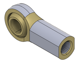
There were several different designs for the connection between the transmission housing and attachment. This part has been referred to as a hitch by the propulsion team to denote the connection it makes. The main goal of this part was to allow rotation about the attachment rod. This goal was developed to make sure that the device would be able to overcome bumps, curbs and other inconsistencies in the road. This functionality was emphasized by some participants in interviews. Many initial designs included shaft collars or different milled aluminum. Shaft collars were used at first because of the ability to detach from the attachment rod. After further discussion, this was determined to not be a vital functionality because of the attachment being removable. Initially, only one connection part was going to be used but two were decided to add stability. The different options of hitches were simplified to the current design which uses two internally threaded ball joint rod ends seen below in Figure 11. This part allows for rotation about the attachment rod because of ball bearings used in the part. Overall, this greatly simplified the design of the hitch and decreased cost and manufacturing time because it is an easily accessible product that performs the needed functions of the connection.
A large concern that was discovered well into the design process was the need to ensure a normal force on the wheel at all times. A spring was decided to be used to ensure that the device maintained a normal force. Calculations were performed to determine what normal force needed in various configurations and inclines and declines. The contributing forces to the normal force calculations were the weight of the device, the force of friction, the normal force, and the reaction forces about the point of rotation. The force of friction was assumed to be the force needed to maintain an orientation of the wheelchair on an inclined plane with a 198 lbs occupant. 198 lbs was used because it is the average weight of an american male [9]. These calculations determined the torque needed from a spring on different types of surfaces ranging from Rubber on asphalt to rubber on wet pavement to simulate different conditions the device would encounter. The static derivation of the different forces and torques can be seen in Appendix B Figure B.18. This is to show the different free body diagrams and equations used to calculate the spring needed. Calculations were done for 12.5%, 8.3% and 5% grades. These were chosen because 12.5% -8.3% is the normal operating range of electric wheelchairs (Table 6) and a 5% grade which is the maximum grade of most pedestrian pathways [7]. The results of these calculations can be seen below in Appendix B Table B.1-B.3.
Based on the calculations, an extension spring was decided to be used because of the higher spring constants and maximum loads compared to torsional springs. Compression and leaf springs were also considered, but determined to be hard to implement. The main need for the spring comes from trying to maintain a normal force when running the motors backwards. This would enable the device to stop on a decline if the spring force was great enough.
Another desired characteristic of spring design was to self contain it into the profile of the prototype to ease installation as well as keep the device safer. An extension spring snapping would pose serious problems so keeping it within the profile of the device was decided to make the device safer. To achieve this, a spring attachment bar was added to the middle of the attachment rod, which can be seen in Figure 12. It is attached using a key and keyway to keep the rod at the same orientation and it keeps the spring extended. U-bolts were used to attach the spring to the bar and to the transmission housing. The spring attachment bar is made out of solid aluminum stock material of 1.5 in thickness.
Calculations were done to determine the spring needed for the device (Appendix B Figure B.19). The attachment bar was calculated to be parallel with the back of the transmission and housing to simplify calculations. A problem that was encountered in this design was that to enable stopping, the spring adds difficulty in overcoming curbs and other obstacles in the roadway when being used. To understand which function was more important to a successful design, our team asked current wheelchair users which function is more important in a device during our stakeholder interviewers. The consensus was overcoming curbs and bumps is of greater importance than braking. For this reason a smaller spring with a spring constant of 5 lbs/in was implemented. This would allow the spring to add some braking capabilities and maintain a normal force going backwards on some declines, but would still be able to extend over a standard curb height of 6 in [7]. Other larger spring constant springs were ordered and tested and deemed to be very hard to extend and not practical to use in the design.
In implementing the spring into the design, creating a perfectly parallel spring attachment bar was difficult and shims were needed to be used in the attachment rod to align the slots better. This was done initially to align the attachment rods to be parallel to the propulsion system but due to a miscalculation or mismeasurement it was below the expected angle making the spring not extend as much as initially anticipated. To correct this additional shims were added to the attachment rods to extend the spring further. This interfered with the effort sensing strain gages and added an unexpected setback late in the project timeline. The current prototype has a spring extended further than initially calculated for. This means the spring force is larger than expected but does not put the spring at risk of over extending over a standard curb height because of the excess stretch the spring has.
The current spring used should provide a torque of around 19 lbs-in. This would put the stopping capabilities of the device on an incline between 8.3 and 5%. By having this braking range the device satisfies specification P9. Testing is needed Testing is needed to measure the actual braking capabilities.
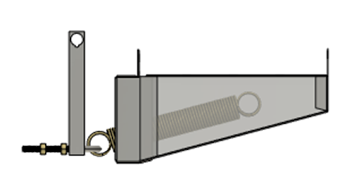
As mentioned, the spring breaking or pinching the user was a concern for safety. For this reason a spring housing was created to conceal the spring. This was done using aluminum sheet metal that was bent. Two separate housings were riveted together to make the complete housing. Two housings were used to better secure the housings to the baseplate and transmission housing. This also allowed for the housing to overhang outside the profile of the transmission housing adding further protection from the extended spring. The complete assembly of the spring can be seen below in Figure 13, which shows the spring, attachment, and housings.
A 48V, 10 amp-hour battery must be used, as this was determined to provide enough energy capacity for this specific motor. To determine the capacity needed, a torque-speed curve was created from the max torque and no load speed of the motor provided by the manufacturer. This linear relationship between torque and speed allows for the torque required to go certain speeds to be determined. Using the torque required to go at a speed of roughly 3 mph, the current that each motor draws per second can be calculated by multiplying this torque by the motor’s speed in rad/sec then dividing this by the voltage of the battery. Using this, the distance needed to travel, and the travel speed, the battery capacity needed can be calculated. These calculations are shown in Appendix B (Figure B.16). As determined by our calculations, this battery will allow for the user to use the device at full speed for 6 miles, and at half speed, the device can be used for approximately 13 miles. This is consistent with Specification 3 and 4. Although the total capacity was calculated, these calculations were simplified as they do not take into account any friction and assume that the user is traveling along a flat surface. The estimation, therefore, for the capacity needed is a small underestimate of how much capacity is actually needed and these calculations would not work if the wheelchair was traveling up an incline.
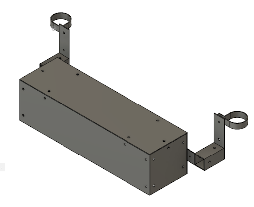
In order to store the battery and to protect it from outside influences such as bumps and weather, a simple battery housing was constructed which can be seen in Figure 14. The housing consists of walls made of 1/16th inch aluminum sheets that are attached to each other using L-brackets. A simple door is attached to the front of the housing which allows for easy access to the battery in case it needs to be replaced. The battery is attached to the underside of the wheelchair by using two aluminum loop clamps on each side of the frame. The battery is then dropped down an inch before being attached to the loop clamps via a square tube. The housing is placed far enough forward so that it can be easily reached in order to change/remove the battery while being far enough back so that the user does not accidentally damage the battery.