Propulsion Team Overview
End of Year Update
-
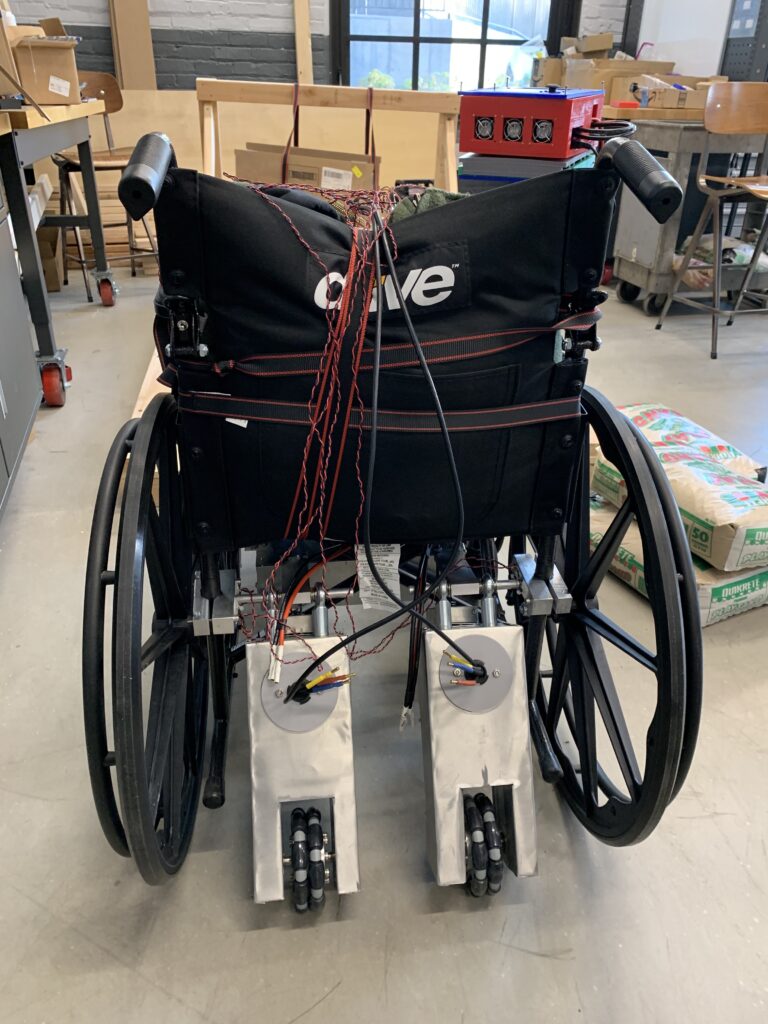
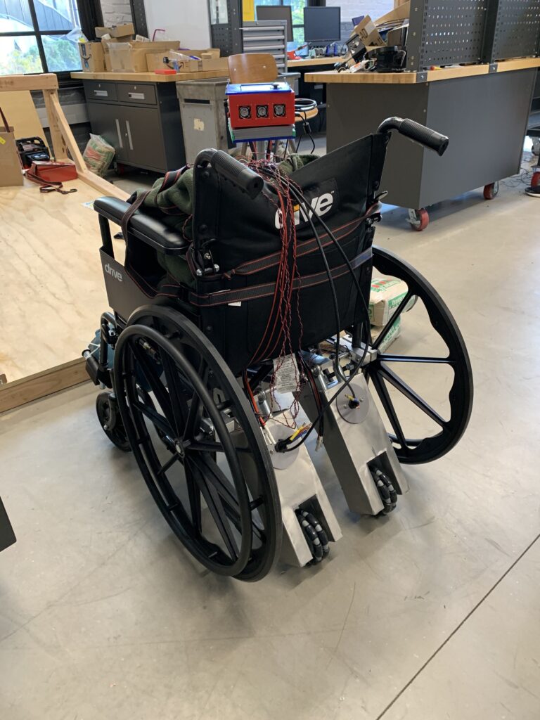
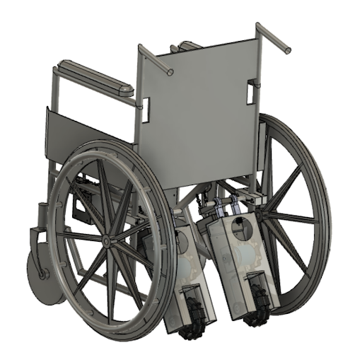
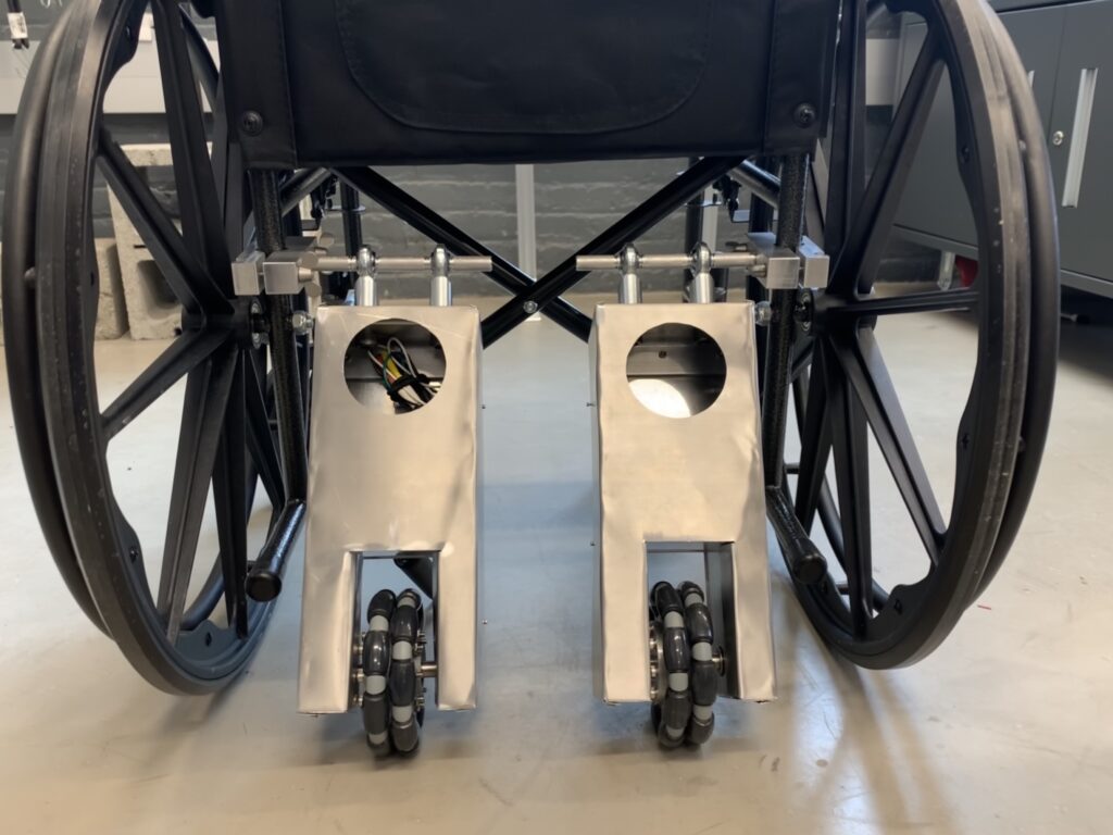
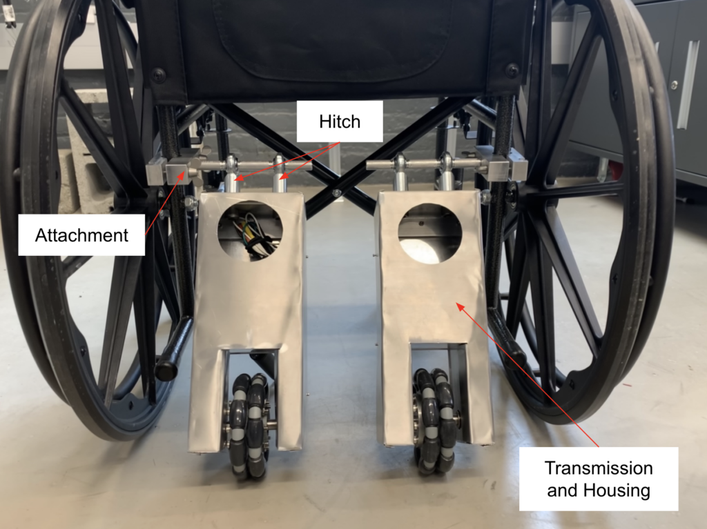
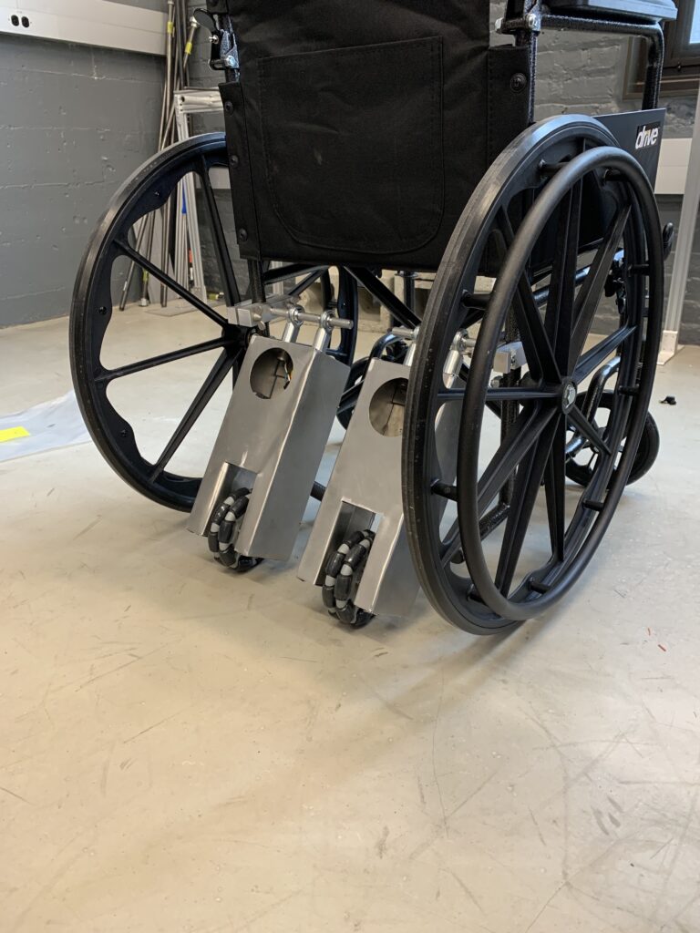
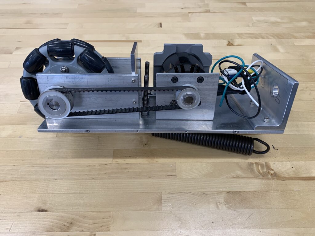
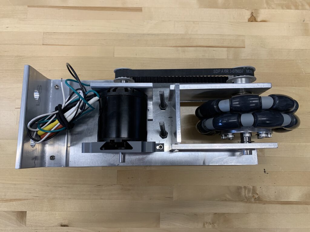
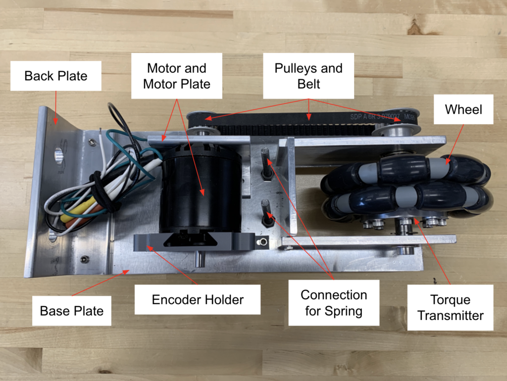
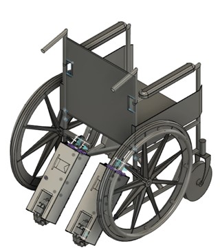
 Figure 5 Propulsion Team Current Prototype
 -
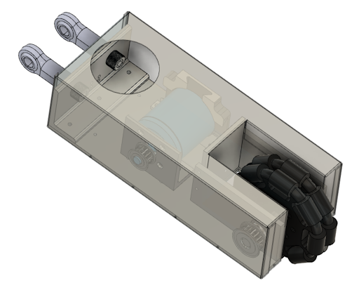
 Figure 6 Transmission and Housing
 -
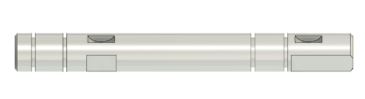
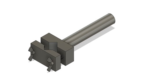
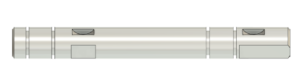 Figure 7 Drive Shaft
 -
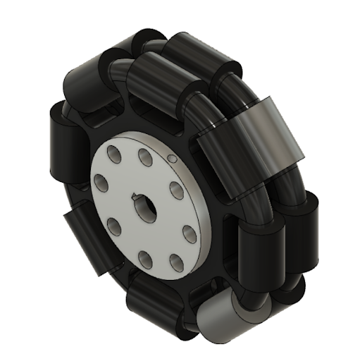
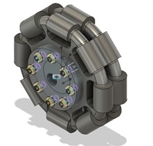
 Figure 8 Rotacaster Wheels and Torque Transmitter
 -
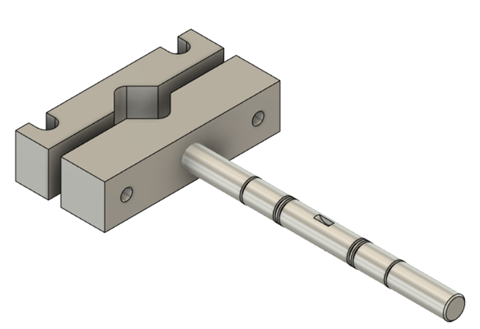
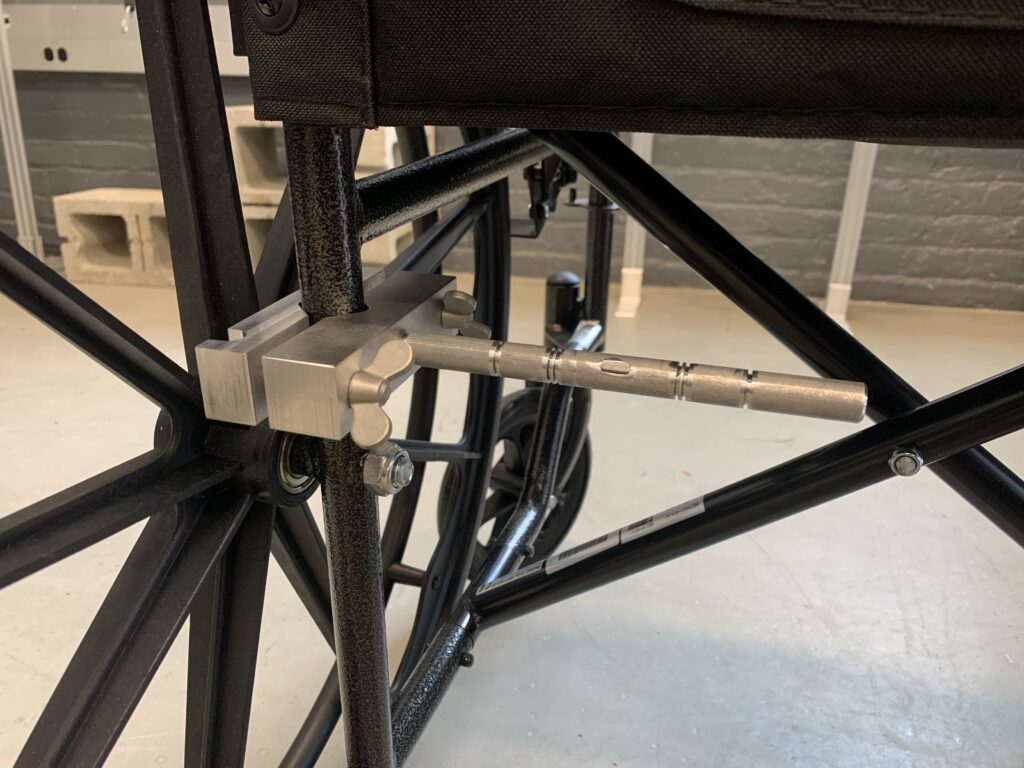
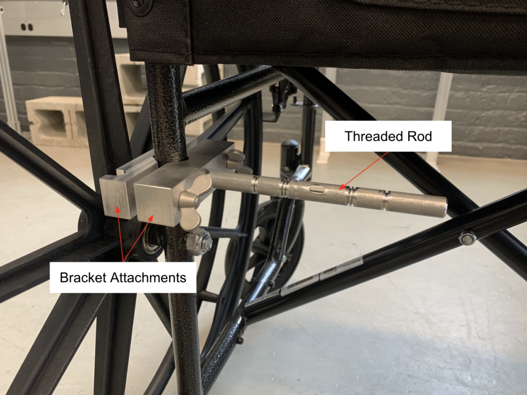
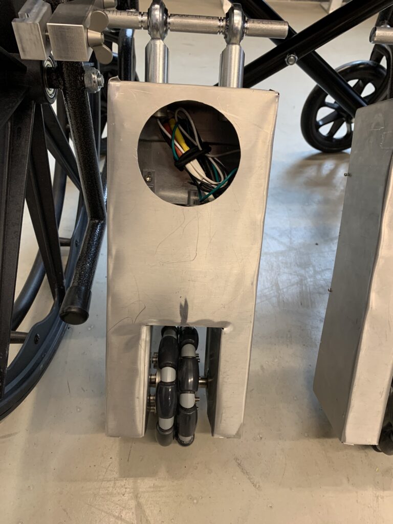
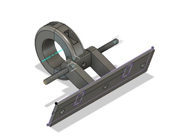
 Figure 9 Attachment mechanism that clamps to the frame of the wheelchair
 -
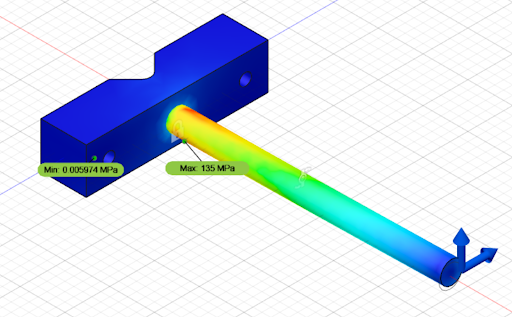
 Figure 10 Stress Analysis on the attachment rod
 -
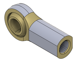 Figure 11 Connection between the transmission and housing and the attachment rod
 -
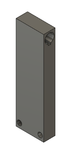
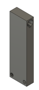 Figure 12 Spring Attachment Bar
 -
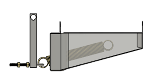
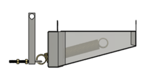 Figure 13 Spring Assembly including the spring, attachment bar and two part aluminum housing
 -
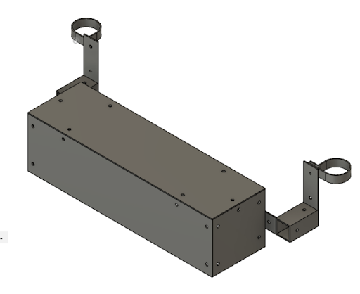
 Figure 14 Battery housing
Progress Update: Mid-March
Motor Test Run
End of the First Semester Designs
Conceptual Designs
-
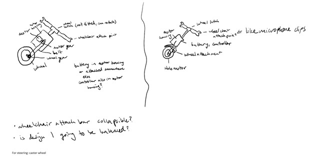 Figure 1 Propulsion system with belt driven wheel
 -
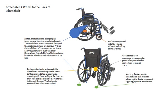 Figure 2(a) Propulsion system with singular wheel
 -
 Figure 2(b) Propulsion system with one wheel possible configurations
 -
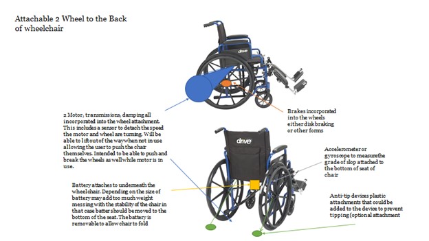 Figure 3(a) Propulsion system with two wheel
 -
 Figure 3(b) Propulsion system with two wheel possible configurations
 -
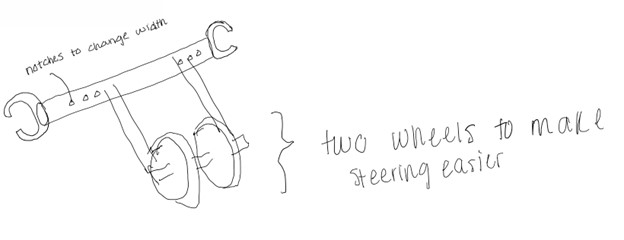 Figure 4 Propulsion system with two wheels
 -
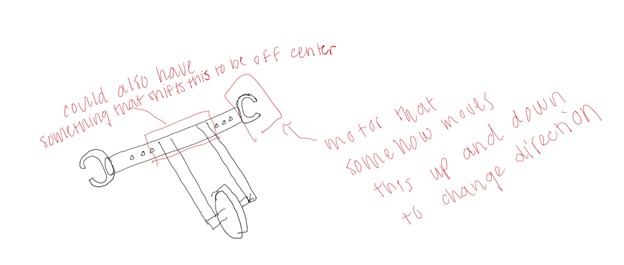 Figure 5 Propulsion system with one wheel
 -
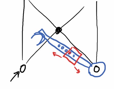 Figure 6 Propulsion system attachments configuration
 -
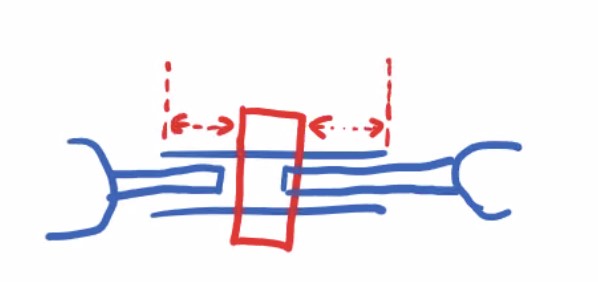 Figure 7 Propulsion system attachments configuration
 -
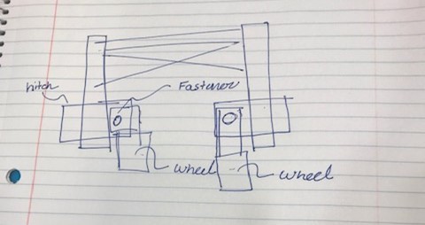 Figure 8 Propulsion system attachment and wheel configuration
 -
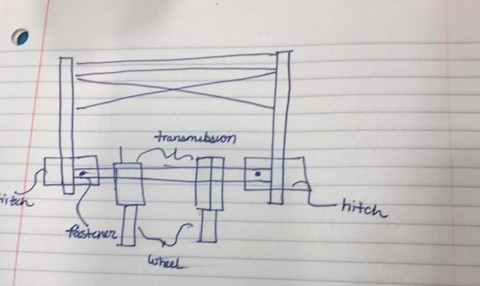 Figure 9 Propulsion system attachment, transmission, and wheel configuration
Calculations and FEA Analysis
-
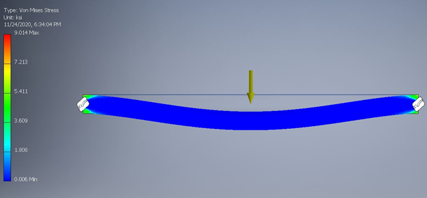 Figure B.14 ANSYS stress analysis for attachment full span shows maximum stress as 9.014 ksi
 -
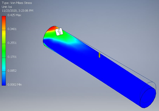 Figure B.15 ANSYS stress analysis for attachment partial span shows maximum stress as 0.425 ksi
 -
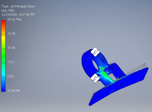 Figure B.16 ANSYS stress analysis for the hitch attachment shows maximum stress of 4.11 ksi
 -
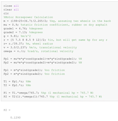 Figure B.17 Motor horsepower calculations in MATLAB
 -
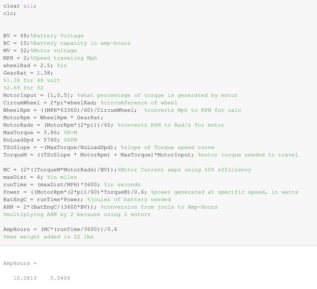 Figure B.18 Battery ampere hour calculations for chosen motor in MATLAB for running motor at 100% and 50%
 -
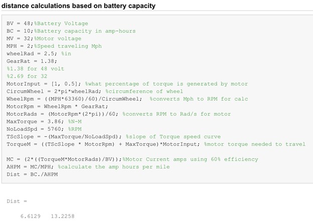 Figure B.19 Distance calculations based on battery capacity for chosen motor in MATLAB for running motor at 100% and 50%
 -
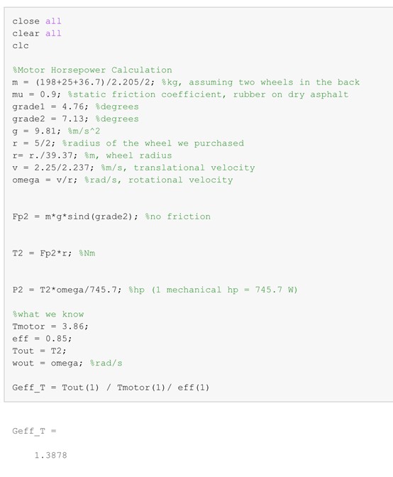 Figure B.20 Gear ratio calculations in MATLAB