The goal of this test is to determine if the propulsion force measurement using the strain gauge measurement apparatus is within the percent error stated in the specification report. Similarly, this will also ensure the horizontal propulsive force, applied by the propulsion subsystem, is being properly isolated by the measurement system. This test will test for Specification ES2 [Appendix A].
Procedure
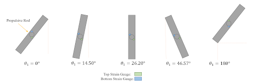
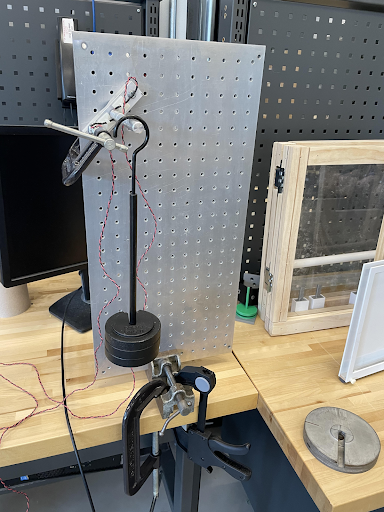
- Attach the strain gauge measurement system attachment to the apparatus shown in figure _ at the specified angle from table 8 (use trig to ensure proper angle). Use bolts to screw it into place or clamps as necessary (depending on the angle).
- Turn on the strain gauge measurement system by booking up the arduino to the computer.
- Hang the weighted hanger on the rod. Record the strain gauge reading output by the subsystem.
- Increase the mass at this angle by adding approximately a 0.5 kg weight to the hanger. Repeat this step for all of the mass requirements listed in the table per angle. The mass should have a minimum of approximately 0.5 kg up to 2kg in increments of 0.5 kg.
- Repeat steps 3 and 4 for the different angles of the rod specified in the table below
Table 8 Specification angles of the propulsive rod and weights for testing.
| Angle of the Rod (1) [degrees] | Minimum Weight Applied [kg] (+/- 0.005 kg) | Increments of Added Weight [kg] (+/- 0.005 kg) | Maximum Weight Applied [kg] (+/- 0.005 kg) |
| 0 (strain gauges parallel with the top of the plate, bottom gauge on top) | 0.5 | 0.5 | 2 |
| 14.50 | 0.5 | 0.5 | 2 |
| 26.20 | 0.5 | 0.5 | 2 |
| 46.57 | 0.5 | 0.5 | 2 |
| 180 (strain gauges parallel with the top of the plate, top gauge on top) | 0.5 | 0.5 | 2 |
Required Equipment
- Weights and a hanger
- Vice
- Clamps
- Bolts
- Aluminum sheet with holes big enough for bolts to secure the subassembly in place
Safety
Overall, this test does not have extreme safety concerns. The biggest safety concern was the usage of the heavy weights. To further mitigate risk they were handled with care and the applied weight did not exceed 2 kg.
Results
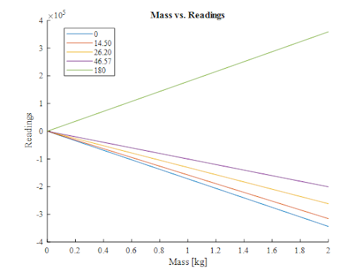
The linear relationship between mass and readings and similarly moment and readings were found using these tests and were linear. This linear relationship was used in the arduino code to calibrate the readings produced by the sensor and properly determine the force. When calibrated, the mass readings were accurate at approximately +/- 0.2 kg which meets the specification goals. Also, it was determined as angle changed, the readings changed proportionally based on the angle as seen in the figure below.