In 2012 I became interested in general aviation and in flight simulation, and I purchased X-Plane 10 and Saitek yoke and rudder pedals. After obtaining my private pilot’s license in 2014, I realized how my simulator setup felt like a game played at a desk and nothing like a real aircraft. It wasn’t until I was slated to teach a freshman writing course at Lafayette College Fall of 2017 on the topic of aviation that I decided to make my simulator as realistic as possible, allowing students to use it as part of the course. This page documents the result of that effort, and I hope it can be a source of inspiration for others who are looking to take their flight simulators to new heights.
Physical Design
One thing I feel is important for a flight simulator is that you feel like you’re inside of something and it probably should even feel a bit cramped if you’re simulating a small GA-type airplane like the C172. Also, being able to see other people or objects in the room destroys the realism, so I needed some type of enclosure.
What I came up with was to weld a metal frame using steel stock (square tube and angle) using a stick welder. Luckily, there are good steel suppliers in the Lehigh Valley Area, and I purchased 96 ft of 1″ square tube and 20 ft of 1″ steel angle for $90 from Orkin Steel. The frame was basically a rectangular box, where a floor and seats were mounted on the bottom, doors were mounted on the side walls, and monitors were mounted on the sides and front.
The steel frame is not one solid piece, because I wanted to be able to take it apart and move it (like to campus where I would be teaching the class). So, it comes apart into 4 main pieces: bottom, left and right sides, and the holder for the computer. Also, separate pieces were welded for the TV mount and vertical monitors on the sides.
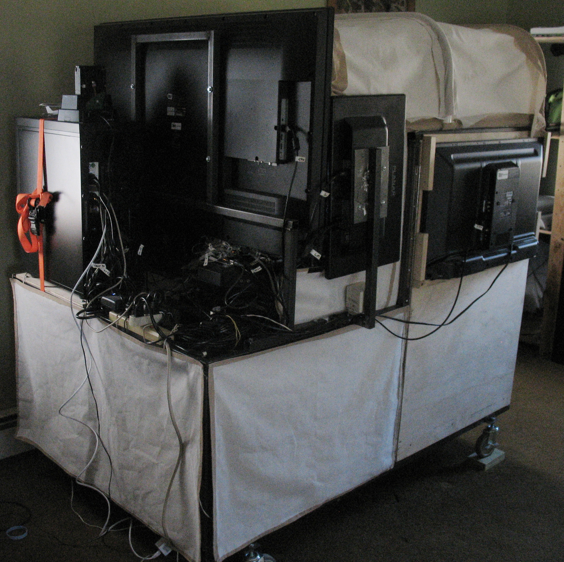
To cover the top, I made a frame out of PVC pipe by heating it up and bending it to conform to a drawn pattern. The PVC frame and sides of the box without monitors were then covered with fabric. The figure below gives you an idea of the result:
I know that it kind of looks like a covered wagon, but mostly you just want to feel enclosed, and when you’re flying the plane, you don’t look so closely at the covering.
Note that I could not afford nice C172 seats, and opted for cheap $40 boat seats. They are uncomfortable, though, and will eventually be upgraded.
Displays
For the windows, I used 5 total displays:
- One 50″ TV for the front center.
- Vertically mounted 22″ monitors for the left and right front.
- 32″ TVs for the windows in the left and right doors.
You might wonder why I bothered with the small monitors on the front left and front right. In a real GA plane, before you taxi across a runway, you really should look to make sure no one is on final who will run into you. Being able to look sideways out the front cockpit window is really helpful. I already had the 22″ monitors, so I used what I had to save money. Probably it would have been better to get taller monitors.
Instrument Panel
The instrument panel was designed in Fusion360 and 3D printed in 3 pieces with PLA using a large 3D printer from Cultivate3D (“The Beast”) that has an 18″ x 18″ print area. The three panels were sanded to obtain a smooth finish and then plastic welded together using a soldering iron and extra filament. Looking back, I probably would not try to 3D print them again. You would be better off using some type of CNC arrangement.
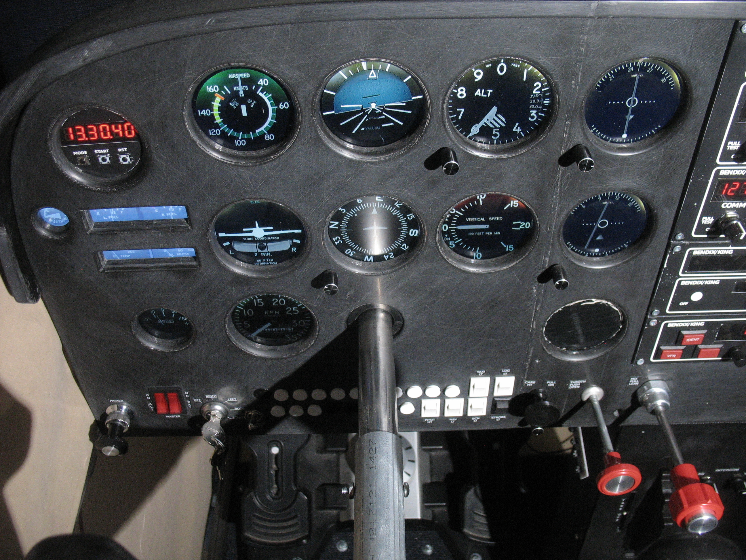
The photo below shows a closeup of the main part of the instrument panel. You can see some artifacts where the pieces were joined together on the right, but again when you are flying, you will not notice. And, let’s face it, most C172s you will fly are pretty beat up anyway.
Gauges
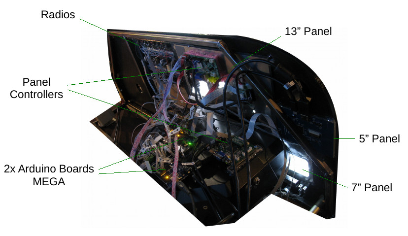
The 3D-printed panel has holes in it where the gauges are, and the gauges were created by mounting three LCD panel monitors behind them. I could have used one big monitor to cover everything, but I didn’t like the idea of the yoke being below all the instruments. There is a 13″ panel that almost perfectly fits the 2×4 array of gauges above the yoke (6-pack plus two VORs). The tachometer and ammeter are covered by a 7″ panel on the bottom left. Finally, the gas gauges, oil temp/pressure, and vacuum gauge are covered by a 5″ panel. Note that the clock/timer in the upper left was made out of 7-segment LED displays and some buttons connected to an Arduino.
Here is the instrument panel from the back showing how the monitors are connected:
I will explain the mess of wires in the section on hardware.
Controls
I tried to make the pilot controls at realistic as possible given my budget, as described below. Note that all of the electronic controls go to two Arduino boards.
Yoke / Rudder
The yoke and rudder panels are just standard Saitek fare. I did modify the Saitek yoke to have a longer shaft, but it still does not have the pull range of a real C172 yoke.
Pulls (Mixture, Throttle, Carb. Heat)
The mixture control is a real vernier mixture control that I got from Aircraft Spruce for around $100, which is connected to a linear potentiometer and read with an Arduino. The throttle control is actually another mixture control, but one without the vernier adjustment. Maybe eventually I’ll get a real throttle control. The carburetor heat was made by 3D printing a knob and attaching it to a wire. The wire goes through a 3D printed holder that I designed that attaches to the panel and holds a linear potentiometer. The potentiometers connect to Arduino analog inputs.
Light Switches
The light switches are cheap rocker switches I bought from Amazon.
Circuit Breakers
The circuit breakers look pretty realistic in the picture, but they don’t actually do anything. They are just 3D printed caps that stick into the holes.
Key Switch
Finding a key switch with 5 positions (off, left mag, right mag, both, start) was not easy. I paid about $50 for that switch from Desktop Aviator.
Master Switches (Alternator / Battery)
That switch is a cheap boat rocker switch. The switch I bought had big 1’s and 0’s on it, which I was able to clean off using acetone.
Primer Knob
The primer knob is not actually connected to anything, but it is a real C172 primer assembly I bought from E-bay for around $80. Nice to have so you practice making sure it is locked in your checklist.
Gauge Adjustment Knobs
Having knobs to adjust the altimeter, heading indicator, and VORs is kind of important, but it was also tricky to get them in there. For each gauge knob, I left a rectangular hole in the back of the instrument panel in the 3D model. This allowed me to put a small rotary encoder there with the shaft sticking out the front of the panel. Having the rotary encoder inset into the panel allows the monitors to still mount flush on the back of the panel so there is no gap in the gauge holes.
Radio
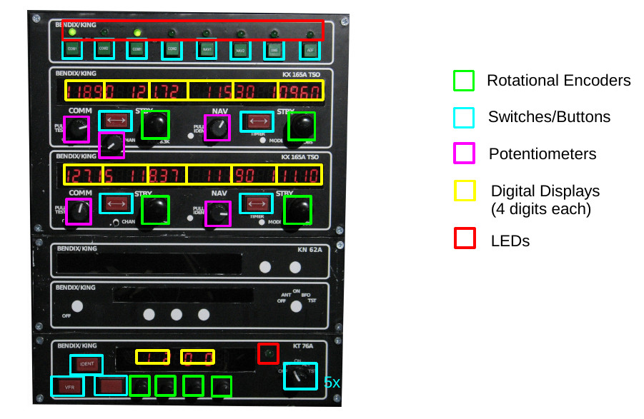
The radio was probably the most complicated part of the whole instrument panel. I made mine basically from scratch using MAX7219 7-segment displays, buttons. The diagram below gives you an idea of the components that were required:
Each radio component was made by taking a piece of smoked plexiglass and using a circuit-board plotter (a small 2D CNC machine) to cut out the required holes. The 7-segment LED displays were placed right behind the smoked plexiglass, and you can see them when they’re on (I got the idea from my old Dark Tower game). To cover parts that should not be see through and to label things, I bought some industrial grade, 8.5×11 laser printer labels that are for labeling hazmat barrels. I designed the fronts in a graphics editor and laser printed it on the labels. Then I cut out the parts where the 7-segment displays should show through and poked holes for the controls as necessary. I should point out that I leveraged some of the radio layouts from this site:
If I were to redo the radio, I think I would have a dedicated Arduino right on the back of the radio rather than running wires from all those controls. Also, I never did finish the ADF / DME component.
Labeling
At first, I wasn’t sure how to accomplish the panel labeling without some kind of silk-screen machine. In the end I was able to get decent results by buying a label machine that supported printing graphics and could make white-on-clear labels. I can’t remember the exact model, but it is a Brother USB label machine that cost around $70. Before mounting labels, I would cut any extra clear label material off from around the words and then very carefully place it on the panel with tweezers before smoothing it down.
Center Quadrant
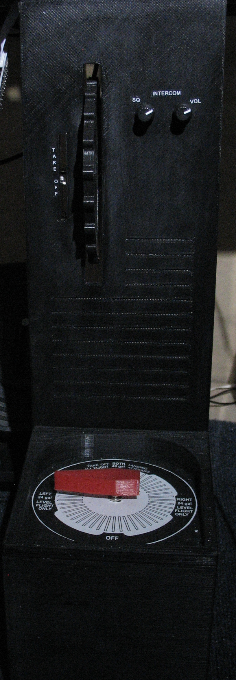
After awhile I decided that not having a fuel select switch in the simulator was bad, because if I used the simulator very much, I found I would start forgetting to check it or switch it to Left/Right after shutdown in the real C172. So, I 3D printed pieces to make a fuel select switch and knob (see picture below). I took a 6-position rotary switch and removed the stops so you can turn it in a full circle. Luckily, this makes it so the four cardinal positions (Left, Right, Both, Off) are at different contact points on the switch, so the simulator can know how you have the fuel select set.
I also printed pieces to make a somewhat crude trim wheel. The trim wheel is connected to a nylon line that moves a linear potentiometer up and down (kind of like the tuning in old radios), which also causes a needle to move up and down to show you your trim setting. With the Saitek yoke, trim is not really useful. But, it is still nice to have so you don’t get in the habit of not resetting the trim before takeoff.
Computer Hardware / Arduinos
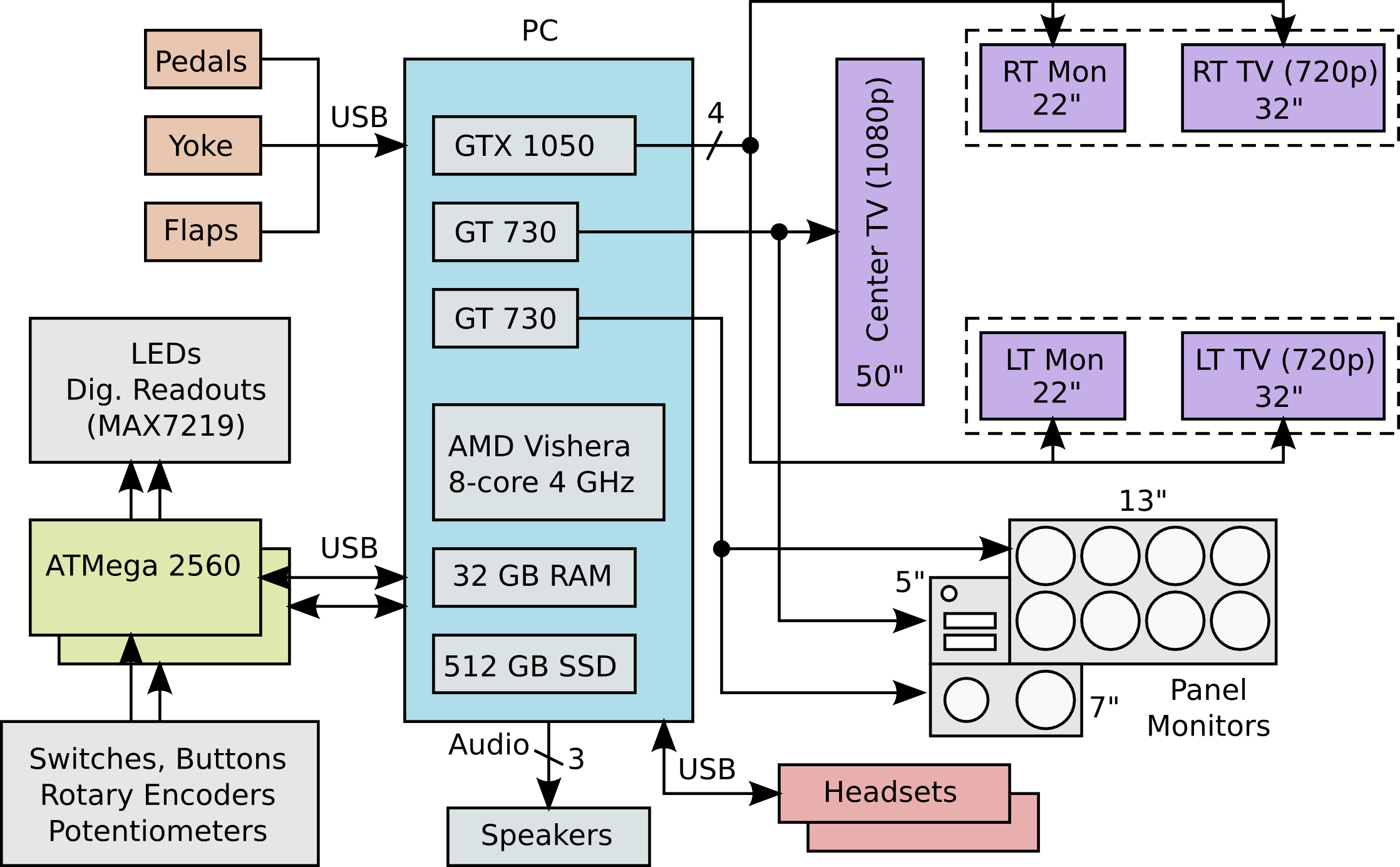
The diagram below gives you an idea of how all the controls are connected to the PC running X-Plane. Since I drew that diagram, I actually upgraded the middle GT 730 to another GTX 1050.
The two Arduino boards are mounted on top of the Saitek yoke, hence the reason for the mess of wires running to them. As I said, a better approach would be to have a separate Arduino just for the radio and make the radio a self-contained unit.
Software Components
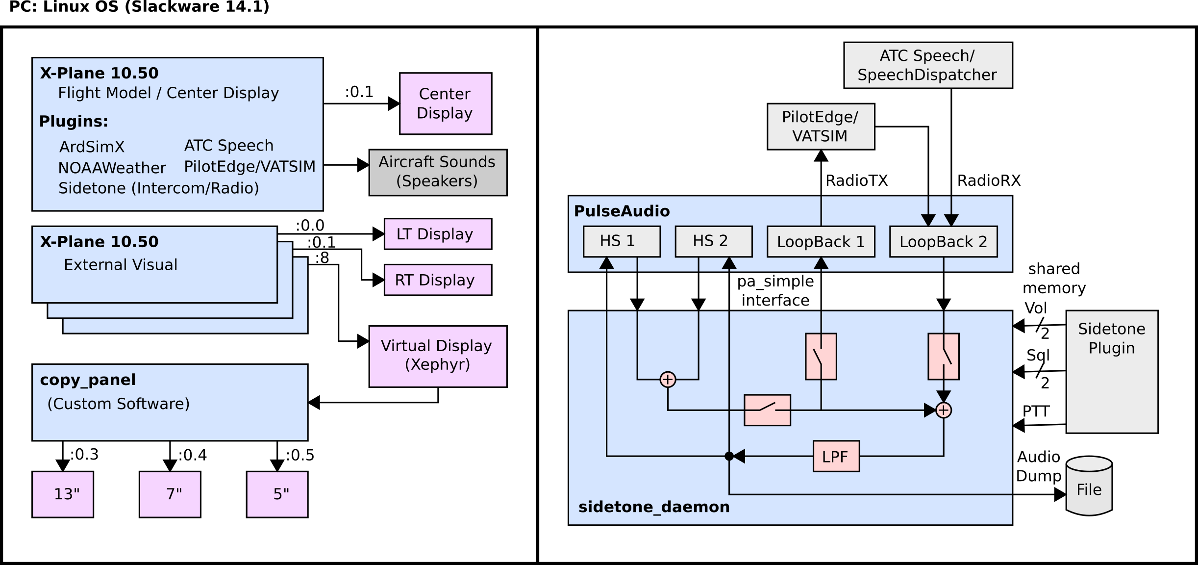
The diagram below gives you an idea of the software components that run on the computer (click on it to enlarge):
The whole system runs on Linux, because (1) it is hacker friendly, and (2) things can be easily automated with scripts. I wanted a system that I could flip a switch and everything comes up on its own. Windows is not well suited for that.
I wrote my own X-Plane plugin which I called “Sidetone” to make headset audio sound more realistic. It does a low-pass filter operation to make the audio sound like a radio, as well as making you “hear yourself” (i.e. “sidetone”) when you press the push-to-talk button. It also does a very basic intercom between two connected headsets. I used PulseAudio for the underlying audio support, which was relatively easy to program. The only problem was getting the latency of the audio loops to be small was not easy. I eventually got what I wanted by tweaking configuration files and such, but a better route would be to use something like Jack that is made for this. The sidetone plugin/daemon can also log all the audio to a file, which is kind of nice to log comms from a flight and be able to play it back to others.
The way I did the graphics for the gauges is a bit complicated, but I did not really like other solutions. I wrote a background program called “copy_panel” that copies specified rectangles from one X-Windows screen to another. So, I have an instance of X-Plane that renders the instrument panel to a background X-Windows screen (using Xephyr), and then copy_panel copies the graphics from each gauge I care about to the instrument panel screens. It’s a bit crude, but it does work in real time and only takes about 50% of one CPU core.
Demo Videos
Here I plan to post a few videos showing the operation of the simulator (work in progress). If clicking the links below does not work, try right click and “open in a new window.”

