
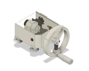
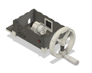
The electro-mechanical design subteam consisted of Garan Comfort and Israel Montero. Over the past year, varying goals and necessities of other subteams greatly influenced the electro-mechanical design of the simulator. These changes can be seen in Figure 1, which demonstrates the adaptability of the design over the past year. These adaptations were built upon the following goals the team set out for the design.
- Produce an inexpensive design which would aid in the decreasing the overall cost of the lathe simulator
- The mechanical design should be a medium for accurate haptic feedback and should provide a sense of realism similar to the lathe drilling process
- User-friendly design
- Easy to ship
Throughout the first semester, the electro-mechanical design revolved around the materials needed to produce realistic haptic feedback derived from data collected from the lathe. The first iterations consisted of a design that held the basic components necessary for the lathe simulator to operate. For the second iteration, a more sophisticated design was produced in order to test the teachability of the lathe simulator on users. The lastest design embodies the goals previously stated and was reduced in size to compactly fit important components.
Accomplishments
I. Inexpensive Design
One of the main goals that the team strived for was to make the lathe simulator inexpensive in order to make it as accessible to users as possible. To achieve this low-cost lathe simulator, the mechanical design of the simulator consisted of 3D printed material and laser cut acrylic. Both were used to reduce the cost and manufacturing time.
In terms of the electronics used within the simulator, the costs were kept down by integrating the simulator into as few parts and connected as possible. Using a PCB isn’t only inexpensive from a manufacturing standpoint, it also reduces the labor that is required to connect all other components in the way that the original prototype was assembled. The cost of other electronics selected to interact with the PCB were also kept to a minimum by choosing widely available parts such as Arduino Nano’s as a microcontroller in charge of interpreting logic, and a motor controller based on widely available high current H-bridge transistors. The other components such as the motor were chosen for their physical capabilities as well as availability through a major supplier like Pololu. The other components such as the e-stop button and fan were inexpensive and available through Amazon. The electronic components of the simulator make up most of the cost, especially the motor, being the most expensive part at $40 per unit. The total cost of the simulator components adds up to a per unit cost of $115.
II. Efficient Medium for Accurate Haptic Feedback
One of the most important aspects of the mechanical design that aided in the realism of the lathe simulator was the handwheel design. To best mimic that handwheel on the real lathe the team created a CAD replica of the handwheel on the lathe and 3D printed the part. In addition to this the team ran data collection trials on a machine shop lathe as outlined in the next section to understand the torques the user would feel based on drill depth and drilling speed. This data was used as a baseline for the motor torque and angular velocity requirements. All electronic components necessary to produce the realism of a lathe are connected through a PCB designed to support an arduino nano, Pololu motor, motor controller, and E-stop button.
III. Easy to Ship and User Friendly
To ensure the simulator is able to ship easily and at low-cost, the team made sure that the simulator fit in a large USPS flat rate box. The dimensions of the simulator currently are 4.5″ x 5.75″ x 3.25″ which fit within the large flat rate box which has dimensions of 12 1⁄4″ x 12 1⁄4″ x 6″. The team also made a user friendly design that allows the user to simply plug the device into an outlet to provide it with power. To make sure the simulator does not move while in use, a screw-clamp design was produced that makes it easy for the user to screw the simulator on a table edge with no additional tools necessary.
Newest Generation
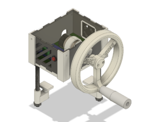
Taking on the third generation of the simulator seen in Figure 1, the design team hoped to fulfill the few final goals of decreasing the size of the simulator housing, as well as decreasing the complexity of the wiring. To do this, a second revision of the PCB was developed in a compact footprint that could use the motor controller and arduino as shields, eliminating the need for breadboards within the housing entirely. All connections are now through the PCB with the exceptions of the wires that lead power into the housing and the wires that input encoder data to the arduino. The final revision also eliminates the load cell in the handle, also eliminating the need for a slip ring. The handwheel is now one solid piece and connects directly to the motor’s output shaft. To secure this simulator to the working surface, the mounting bolts are now integrated into the body of the simulator eliminating the need for additional c-clamps that were required to secure the second generation to the table. A clear acrylic top was used to allow users to view the inner workings of the simulator and teach about haptic control systems in a visual way.
   |
|
Figure 1. First, second and third iterations of electro-mechanical design. |
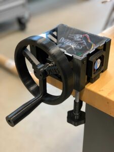 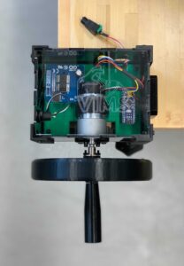 |
|
Figure 2. Final Simulator design, fully assembled. |