Solar Tracker Project
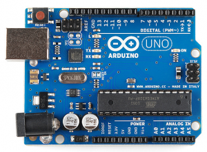
An Arduino is an open-source electronics platform based on easy to use hardware and software. That is the nerdy definition of it! To explain it in another way, it is mini electronic cardboard that you can use to do electronic prototyping. You can do almost anything from it from blinking an LED, turning a motor to making your own robot. For an electronic beginner, it is the best material needs to be learned. One of the many Arduino projects that I made is the solar tracker. It is a solar panel that tracks the sunlight instantly.
Why a solar panel that tracks the sun matter?
Solar panel uses sunlight to produce electricity. The more it receives sunlight, the more it produces electricity. A classic solar panel orients in the same place during the whole day. Yet, the sun moves from the East to the West every day. Therefore, the production efficiency is low. On the other hand, if the solar panel receives a constant maximum light, the electricity production can be a way bigger. That is why I wanted to build one as a little project.
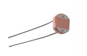
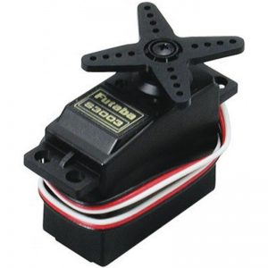
For that project, I used an Arduino microcontroller, a mini solar panel, 4 photosensors, 2 servo motors, one water can, woods and wires. The aim of the woods and water can is to build the support of the entire system. Some people use 3D printers to design it but I did not have access to 3D printers so I made it by hands.

The solar tracker that I made is a dual axis solar tracker which means that it can rotate from up to down and from right to left. The general principle of this tracker is the following:
- 4 photosensors which are placed in the top, down, right and left are used to measure the light.
- the servo motors will rotate in function of the difference of measurement between the sensors.
Let’s say for example that the photosensors from the left of the solar tracker receive more light than the one in the right. In theory, both of them receives orients in the maximum amount of light if they have the measure the same light. Therefore, to reach that purpose, the Arduino was coded to rotate the servo motors in the left until that purpose is attained. The same principle applies from the up and down sensors.
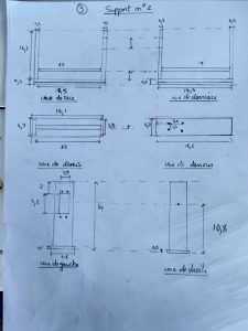
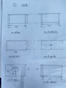
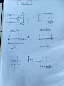
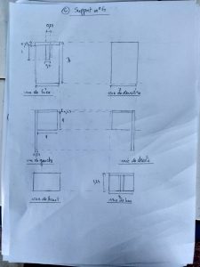
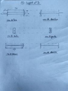
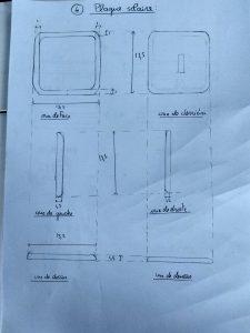
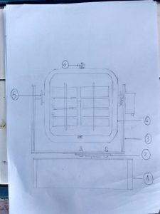
When I designed the whole system, I tried to realize it by hands first. The following photos detail the dimension of each element of the solar tracker.
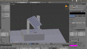
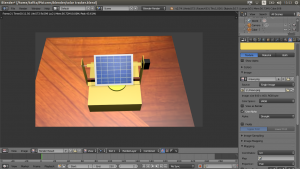
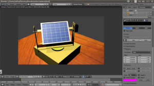
After the hand made drawing, I made a 3D model in the Software called blender. A 3D model gives a good idea of the system as a whole.
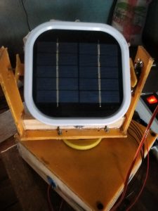
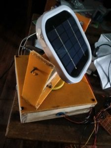
After the 3D model, I built the solar tracker system part by part. Using a 3D printer would take me less time but it was hard and expensive to find one in Madagascar. Thus, I had to do it by myself with a little help from my brother. The result of the project looks at the following. My mistake was the fact that I did not take a lot of pictures to show.
This solar tracker worked perfectly but in my case, there was still a limitation. The solar panel that I used myself is an old solar panel that I reused so it was not able to power the Arduino. Therefore, I used an external source. However, in the real world, such technology already exists and it is able to power itself and at the same time produce for the people. For me, it was a positive project because I learned a lot of things: from thinking about the code and circuits of the system into transforming water can into solar tracker support.
PS: I have not worked on the more technical explanation of this project but I am working on it. I will share it when I am done with it.
Demonstration video :
Leave a Reply