Here is a short video of the led cube.
It is a good project for practice if you dont know how to solder. This was my first time soldering too, and it was a pain in the beginning. I am not so bad now that I’ve had some practice :).
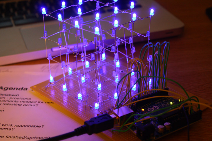
The ledCube is really just a cube of leds that is controlled by an arduino. It consists of 4 layers stacked on top of each other with 16 leds in each layer. All the leds in a layer share a cathode – so there are 4 cathodes in total. All the leds in the vertical column share an anode – so there are 16 anodes. This makes a total of 20 pins, which is perfect since the arduino uno has 20 input/output pins (including analog and digital pins).

To make the cube, I made this jig by drilling holes in a wooden plate. The holes are around 25mm ~ 1in apart – thats the length of my cathodes. I bent all the cathodes in a layer and soldered them together. I made 4 of these layes and soldered all the anodes in different layers together. It was a lot of soldering and I did make a lot of mistakes. I even melt one of the leds 😀
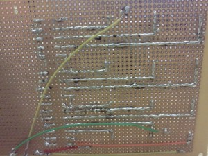
Once this was done, I attached my cube to a perfboard, connected each anode to a 100ohm resistor and then to a wire. I connected all these anodes and cathodes to my arduino and wrote some simple code to test it. I intend to tinker more with the programming once I finish my finals.
Here is the code:
//led cube test code - by ritesh maharjan

//define the pins to control the anode and cathode
int ledPin[]={0,1,2,3,4,5,6,7,8,9,10,11,12,13,14,15};
int layerPin[]={16,17,18,19};

int delayTime = 50;
long randNO;

//setup
void setup(){

  for (int pin = 0; pin <16; pin++){
    pinMode(ledPin[pin], OUTPUT);
    digitalWrite(ledPin[pin], LOW);
  }

void loop(){
  Rain();
}

//rain - lights move downwwards one column at a time like rain drops.
void Rain(){
randNO = random(16);
  digitalWrite(ledPin[randNO], HIGH);

  for(int i=3; i>-1; i--){
    digitalWrite(layerPin[i], LOW);
    delay(delayTime);
    digitalWrite(layerPin[i], HIGH);
    delay(delayTime);
  }

  digitalWrite(randNO,LOW);
}