Thermal Storage
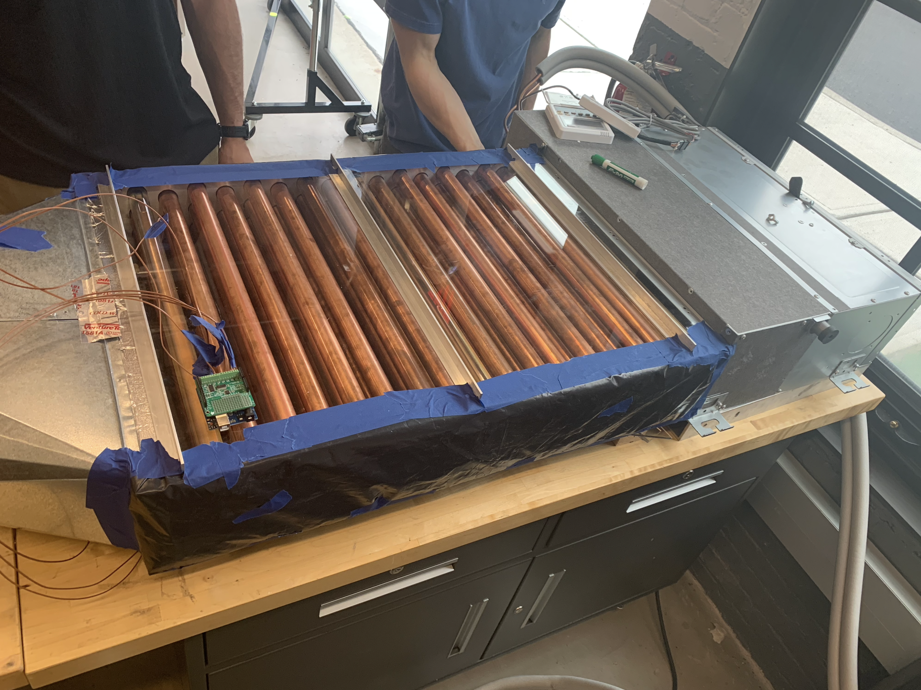
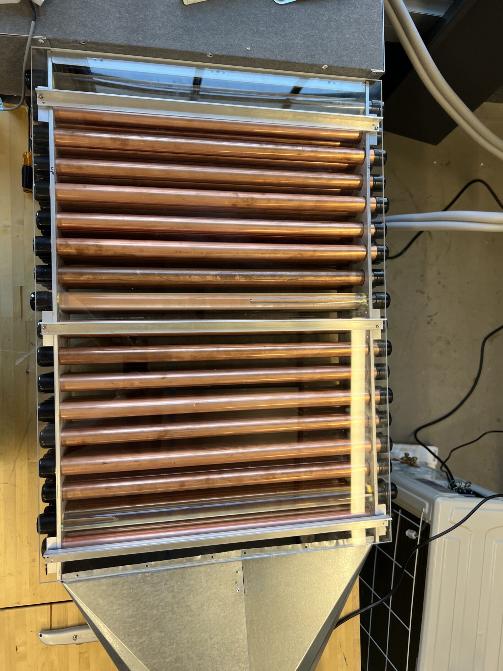
Our beta prototype consisted of the actual construction of the heat exchanger as well as data acquisition, interpretation, and testing to empirically characterize its performance. From our results and discussions during the alpha prototyping phase, we decided to pursue the staggered PCM filled tubes in crossflow design.With this type of design selected, we started by analyzing parameters including tube diameter, number of tubes, and shell length in order to find which dimensions fit our needs and goals the best. Once the actual dimensions of our design were finalized, we ordered materials including an acrylic sheet, copper tubes, rubber end caps for the copper tubing, etc, and assembled the heat exchanger with the help of the machine shop. In the data acquisition and interpretation phase, we used arduino in conjunction with thermocouple sensors to record data that allowed us to make conclusions about the performance of our design.
With this prototype, we evaluated our team’s functional requirements related to energy storage and testing. After completing construction of the heat exchanger and fully freezing the PCM, we turned off the compressor to ensure that our system can maintain thermal comfort without the use of the compressor, per functional requirements 1.2.1/1.2.2. Per functional requirements 2.2, 2.3, and 2.4, the team took temperature measurements and collected data related to rates of airflow at the inlet and outlet of the heat exchanger in order to verify the ability of the system to maintain temperature and record such data.
As seen in the photos below, the thermal storage heat exchanger prototype is located in-between the commercially available air supply HVAC system and the thermal comfort transition duct:
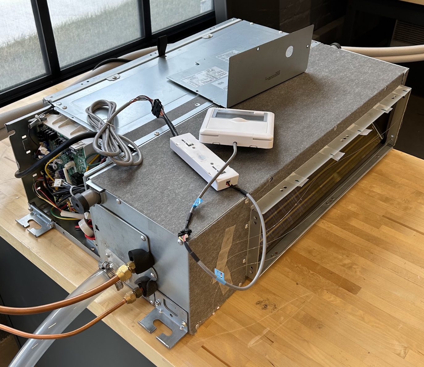
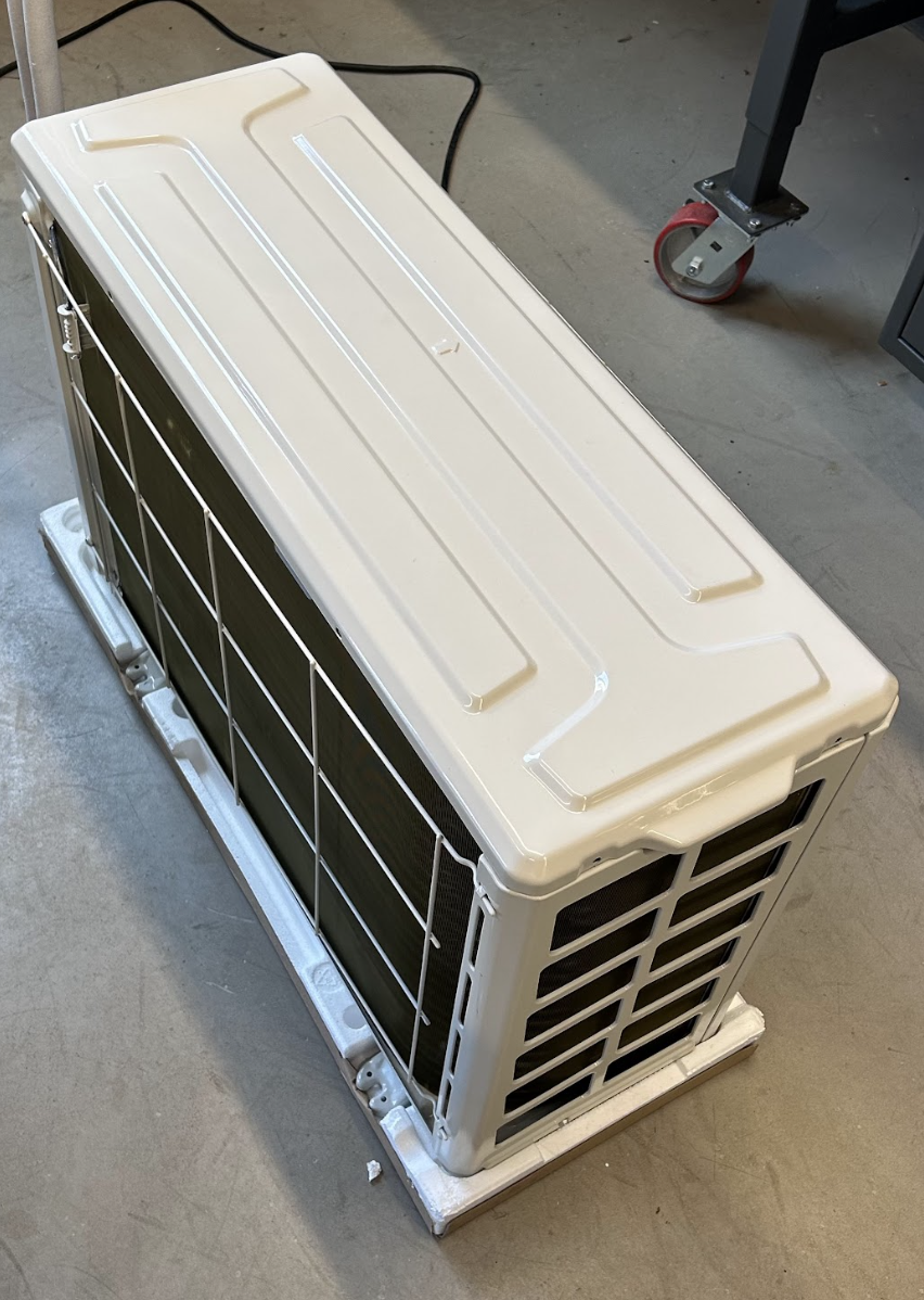
The picture below is the commercially available air supply HVAC system followed by a picture of the compressor/condenser unit which is typically located outside of the building in residential and commercial applications. The refrigerant is circulated between the two components to create cool air coming out of the air supply unit.
Air supply unit:
Compressor/Condenser Outdoor Unit:
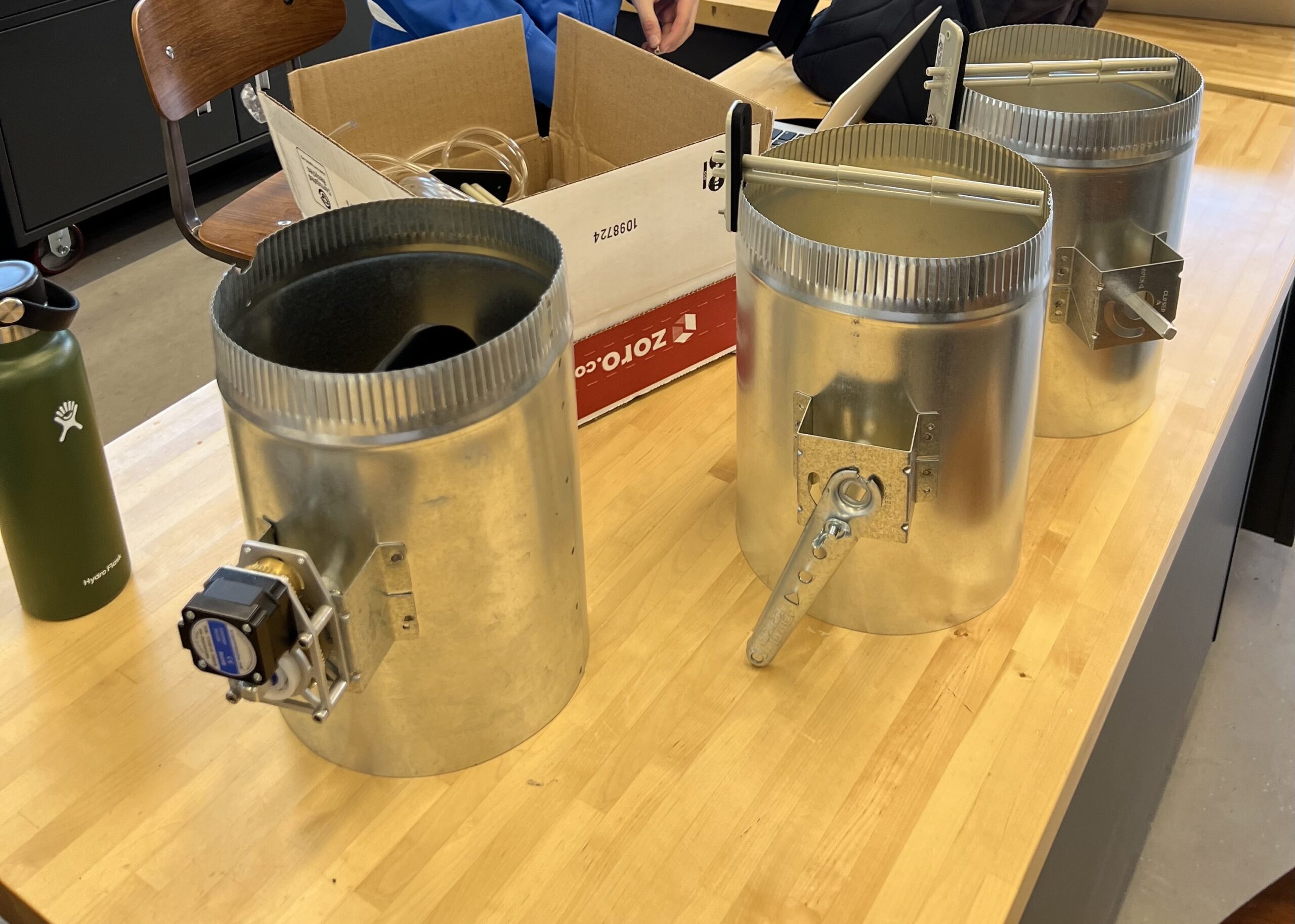
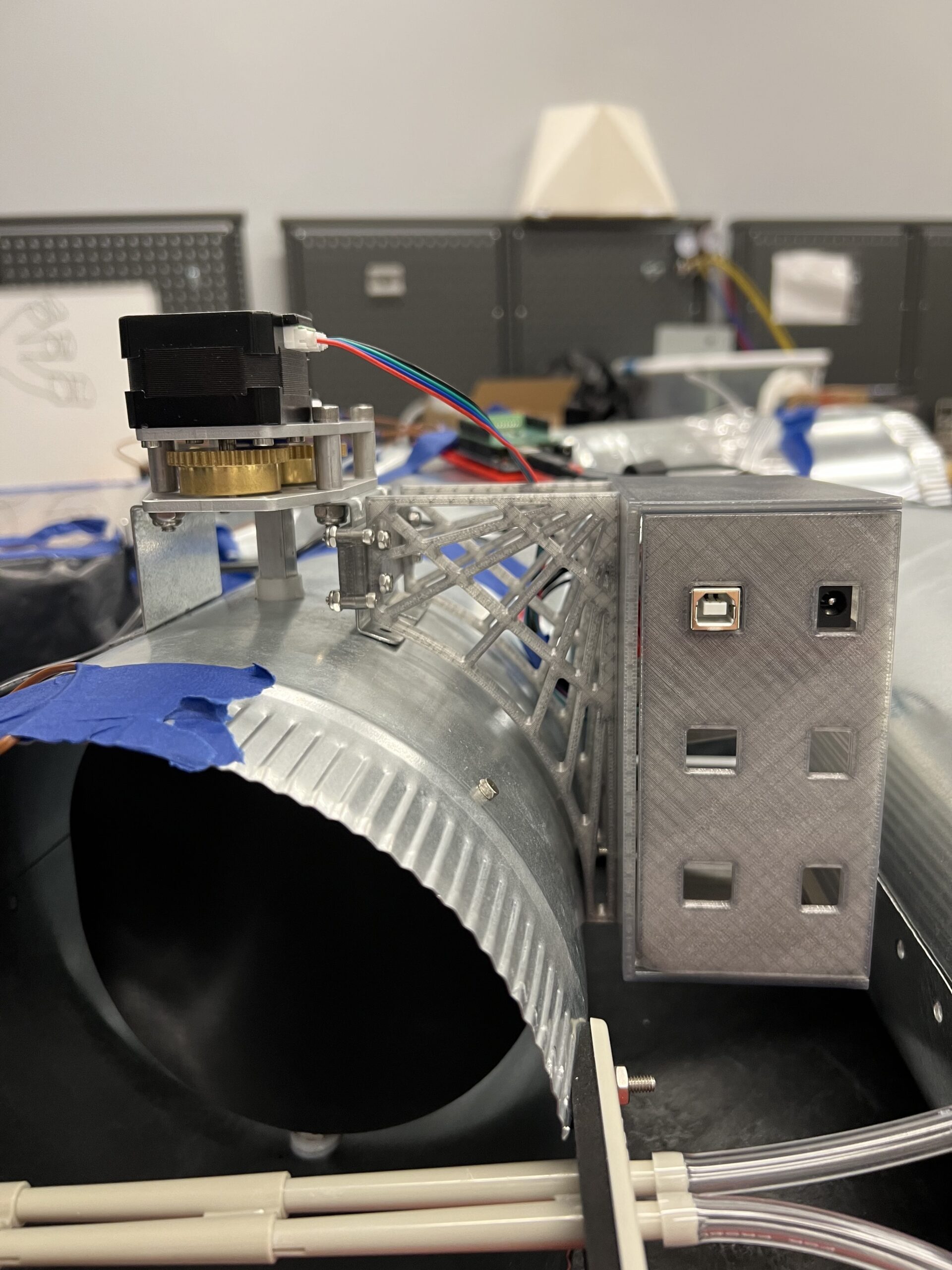
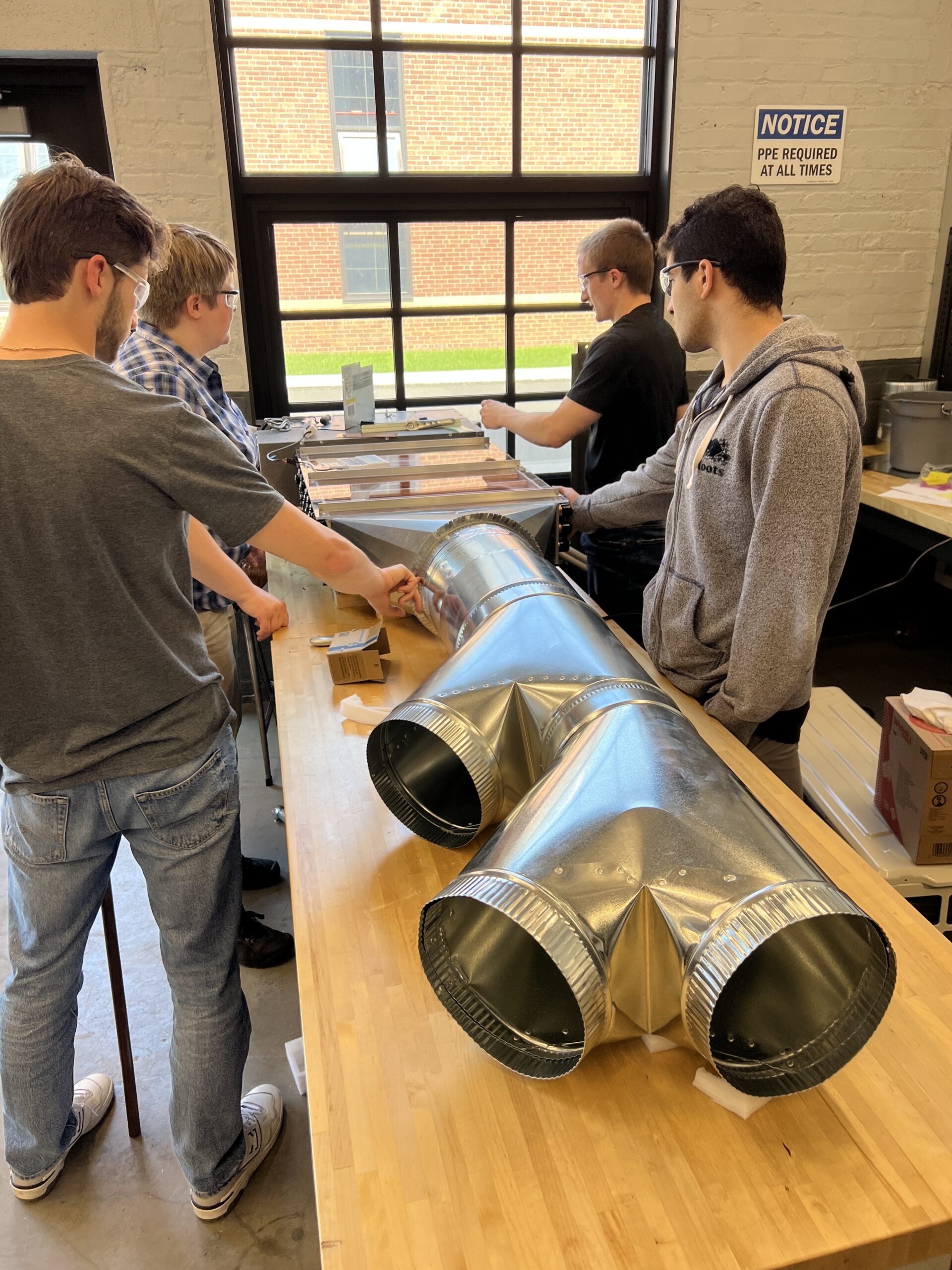
Thermal Comfort
The beta prototype for the thermal comfort team consisted of two main sections. The first part of the prototype included finalizing and actually manufacturing a design for the transition duct between the rectangular ducts of the thermal storage section and the circular ducts that will transport the air to different climate zones. The purpose of this part of our prototype was to ensure that our final design can be connected to and is compatible with the thermal storage team’s heat exchanger design. The second part of the prototype involved designing a system to control airflow using dampers. The overall goal was to create a subsystem that controls indoor airflow in order to moderate the temperature of two different indoor zones. This reflects upon the team’s functional requirement stating the initial need to control temperature and airflow for four different zones. By focusing on two zones, the team decided that they are better fit to understand airflow and what temperature trends arise. We used a variety of sensors and an Arduino to collect data and implement an appropriate control system.