Helios At Lafayette Functional Decomposition
Functional Decomposition is an analysis method that splits a process into individual elements/tasks for visual representation, comprehension, and analysis.
The Helios team used our functional requirements and problem statement to come up with ideas for our functional decomposition. We decided on performing a functional decomposition because it will allow the team to visualize the smaller tasks associated within main system functions, and help the team better understand the total scope of the functions that need to be performed to achieve the end goal. Since our project is headed in the direction of having two linked but distinct functions, the team decided to perform two separate functional decompositions:
- Thermal Storage
- Localized Thermal Comfort
Thermal Storage:
The main function of our Thermal Storage functional decomposition, seen in Figure 1, is to store thermal energy for cooling usage (additional details regarding the type of thermal storage and specifications for thermal storage can be found in our functional requirements). This main function was decomposed into the following subfunctions:
- Read Electric Grid Strain Signal
- This will be required to tell the system when to charge and when not to charge. We want to charge when the grid has a low load.
- Measure Charge Level
- This will be required to know when to stop charging or when to charge.
- Read Indoor Temperature
- This will be required for the system to know when the thermal mass (ability of material to absorb, store, and discharge heat) should be discharged.
- Vary Heat Exchange Rate
- Varying the heat exchange rate will allow us to adapt for different cooling loads.
- Charge Thermal Energy
- This is when the cool air from the system freezes the thermal mass. This will involve heat transfer.
- Discharge Thermal Energy
- This is for when cooling is needed in the house, thus involving heat transfer.
We decided that our system boundary (all considered components of the system) would exclude the system that actually produces the heating and cooling air supply. This impacts our inputs to the system because we can now assume that we are getting hot and cold air at a specific temperature and don’t have to worry about how we are producing that air. The inputs and outputs of our system are somewhat straightforward, but it is important to note that thermal storage is a transient (time-varying) process, so inputs and outputs may change depending on time.
Inputs for the thermal storage functional decomposition are:
- Off-Peak Cool Air
- Warm, Unconditioned Air
- Information Signals
- Electricity (not shown in diagram – we will implement this at a later time)
Outputs for the thermal storage functional decomposition are:
- Cooled Air
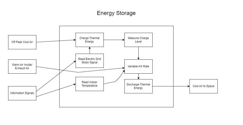
Figure 1: Functional Decomposition diagram for Energy Storage.
Localized Thermal Comfort
A separate but similar problem that we are focusing on is that maintaining thermal comfort within residential environments costs too much over time for their given HVAC systems.
To solve this issue, the main function of our solution would need to control the temperature locally. “Locally” would mean if one room is being warmed by the sun through a window, that room would need more cooling from our system compared to the basement of a home, where cold air sinks and the room is more insulated. Controlling temperature “locally” would, more efficiently, maintain constant comfort dependent on the thermal comfort-affecting conditions of each room, saving energy costs by only using energy in rooms where it is needed.
Following the functional decomposition process, we broke up our main task into the following subfunctions:
- Control System
- Will take the users desired inputs and current conditions to tell our system what to do to achieve the user’s desired conditions.
- Distribute Air Locally
- Will take our system’s input air and move it to wherever our control system tells it to in order to meet the user’s desired conditions.
- Change the Air Temperature Locally
- Will take the desired temperature input and current temperature, changing current temperature to whatever value our control system tells it to meet the user’s desired conditions.
- Minimize Pressure Drops
- Moving air requires pressure changes. Artificially creating pressure changes requires machines and energy to do so, and the obstructions we put between the input air and output air will cause the air to slow down due to pressure drops. We want to minimize the energy losses our system creates so that it requires less energy to function properly.
To create our system boundary we assumed that our system will receive the input of an outside upstream fluid. For example, a vapor compression cycle will not be included in our design, but the output of a vapor compression will be inputted into our system. Our system boundary encompasses the vapor compression cycle output and everything required for local temperature control in each room.
Inputs for the local comfort functional decomposition are:
- Desired mass flow rate of air
- Desired temperature of air
- Current room temperature of air
- Current upstream mass flow rate of air
- Current upstream temperature of air
- Electricity (not shown in diagram because we will implement this at a later time)
Outputs for local comfort functional decomposition are:
- New room temperature of air
- New mass flow rate of air
The interaction between sub functions, inputs, and outputs can be seen in Figure 2.
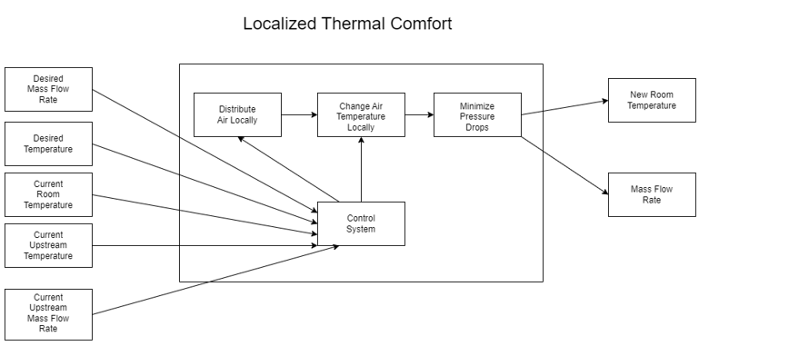
Figure 2: Functional Decomposition for Localized Thermal Comfort.