Thermal Storage
Each design was graded on the general categories of heat transfer effectiveness, pressure drop, manufacturability, and cost. Some of these were eventually further broken down into subcategories for a more in-depth analysis. For heat transfer, the team examined maximizing surface area of the tubes while minimizing the length and volume of each one to allow for assumptions such as lumped capacitance to work better as well as to get more PCM exposed to the air near the outer parts of the copper tubes. Using lumped capacitance allowed the team to estimate a thermal time constant for each design and use that as an indicator of how effectively heat is being transferred between the air and the PCM.
In addition to heat transfer, pressure drop through the exchanger also needed to be minimized, since if there is too much pressure drop the air will not flow effectively through the exchanger and into the duct space. Manufacturability and ease of assembly were also considered, since if a component was difficult or impossible to manufacture and assemble, this would lengthen the limited time we have to develop the prototype. It could also warrant the development of an alternative design. Another constraint is cost, as the team does not have an unlimited budget. We must manufacture a design that will not cost an excessive amount.
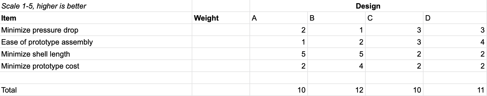
The process of actually grading each design was iterative. The first round of grading involved sitting down as a group and conducting an “eye test” of the four hand-drawn heat exchanger seen in the “Concept Generation” page. The team discussed each factor for each design and using our own engineering intuition to score each design for that factor from 1 to 5. The full matrix for this first round is shown below. The heat transfer categories were omitted from this first round, as the team determined that they required more specific calculations and considerations (such as number of tubes) to be properly scored. After this round of analysis, the team determined that designs B and D would be looked into with more detail, since these designs scored the highest.
The second iteration of grading utilized computational fluid dynamics (CFD) to analyze the four 3D modeled heat exchangers seen in the “Concept Generation” page. The results of the CFD are seen below:
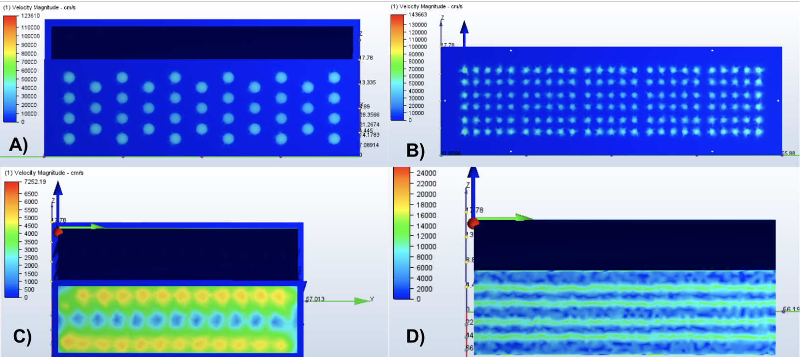
Designs A and B both had relatively high pressure drop and couldn’t hold nearly as much PCM as we needed (5 Gallons). Design C had the least amount of pressure drop but held the least amount of PCM out of the four designs. Design D had the second smallest pressure drop and also could hold the most PCM. Therefore, our analysis for the next prototype will focus on optimizing Design D.
Thermal Comfort
While creating our physical design for our transition piece on poster board, it needed to be sized correctly at the inlet in order to connect with the thermal storage heat exchanger and have the other end sized to fit the ducts. We discovered that we needed to split our design into two pieces to make it easier to manufacture. After splitting it, we learned that an additional inch of material would have to be added to the one side of our design to allow for it to be riveted together. We now have confidence that our design will be manufacturable when working with actual sheet metal. However, we do plan on having additional conversations with the machinists to determine if we need to split our design into three or more pieces to ensure the sheet metal can be easily bent as required. This will hopefully save us time and money when manufacturing the final transition piece.
For the ducts, we needed to ensure that the outlet sizes were large enough to generate minimal outlet flow velocity increases. We also needed to ensure that parts were available from common suppliers at a reasonable price and compatible with existing dampers. Moreover, when considering our functional requirements, our prototype has a three zone minimum design range and required the necessary capability to reach a four zone minimum range by adding an additional duct section. Finally, as our alpha prototype was a computer model of what our beta prototype would ultimately be, we considered the cost of the eventual parts for construction, but cost was not a constraint for the final alpha prototype. We used CFD modeling software provided by the college rather than building a physical test platform. Our CFD simulation showed that air will effectively reach all 3 climate zones even when a damper is completely closed. Essentially, the damper is not able to completely shut off all air flow to a zone. In addition, we learned valuable information about areas in our design that have a significant pressure drop. CFD will be a valuable tool as we continue our project and look further into pressure drops and air flow between the different climate zones.