For the purposes of our project, the alpha prototype served as a precursor to the actual manufacturing process which we knew would ultimately be the primary pillar of our beta prototype. Accordingly, there was no new brainstorming or concept generation stages that our team had to engage with in order to decide on a direction for the beta prototype.
Instead of generating new concepts, the thermal storage team performed a deeper analysis of the finalized heat exchanger design from the Alpha prototype. The thermal storage team started work on the Beta prototype by constructing a mathematical spreadsheet to analyze what size copper tubes should be used and how far apart they should be. The way the spreadsheet worked, is we would input tube diameter and tube spacing, and the spreadsheet would calculate the pressure drop, number of tubes that would be required to achieve 5 gallons of PCM, total length of the heat exchanger, and thermal time constant which is a measure of how fast the tubes will respond to temperature changes. This spreadsheet showed that the tube with the best compromise between these characteristics was a 1” nominal diameter tube.
The team did use the feedback received during the alpha prototype design review to inform our design decisions and make changes before beginning with manufacturing. Those decisions included the following:
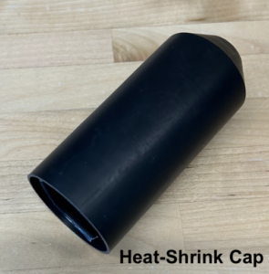
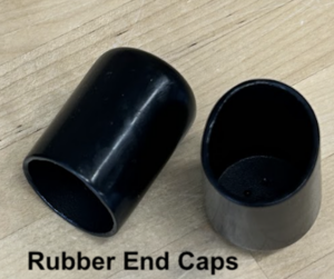
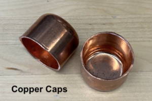
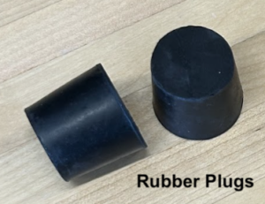
- After conversations with Professor Sabatino regarding potential PCM leakage, the thermal storage team ordered many sealing options for the PCM tubes to test. We ordered a heat-shrinking cap, rubber end caps, copper caps and rubber plugs, and ultimately decided on the rubber end caps and rubber plugs. The heat-shrinking caps were too expensive and time consuming to install, the copper caps proved too difficult to permanently attach, and the rubber end cap ended up being the best choice for its quick and easy installation.
- The thermal comfort team decided that it made sense to reduce the number of zones to which we want to be able to control the airflow from four zones to two zones as our design is such that another zone can easily be added.
- The thermal storage team ignored the capacity requirement as our original requirement stated that the “thermal storage capacity of the 1/8th scale prototype system should be at least 17-41.5 MJ” and our calculations after the initial purchase of 5 gallons of PCM showed that our system could store 2.96 MJ. Our prototype ended up being below a 1/8th scale prototype, making it difficult to quantify a capacity requirement.
Damper control design selection:
- We evaluated different designs using the Pugh Matrix shown below:
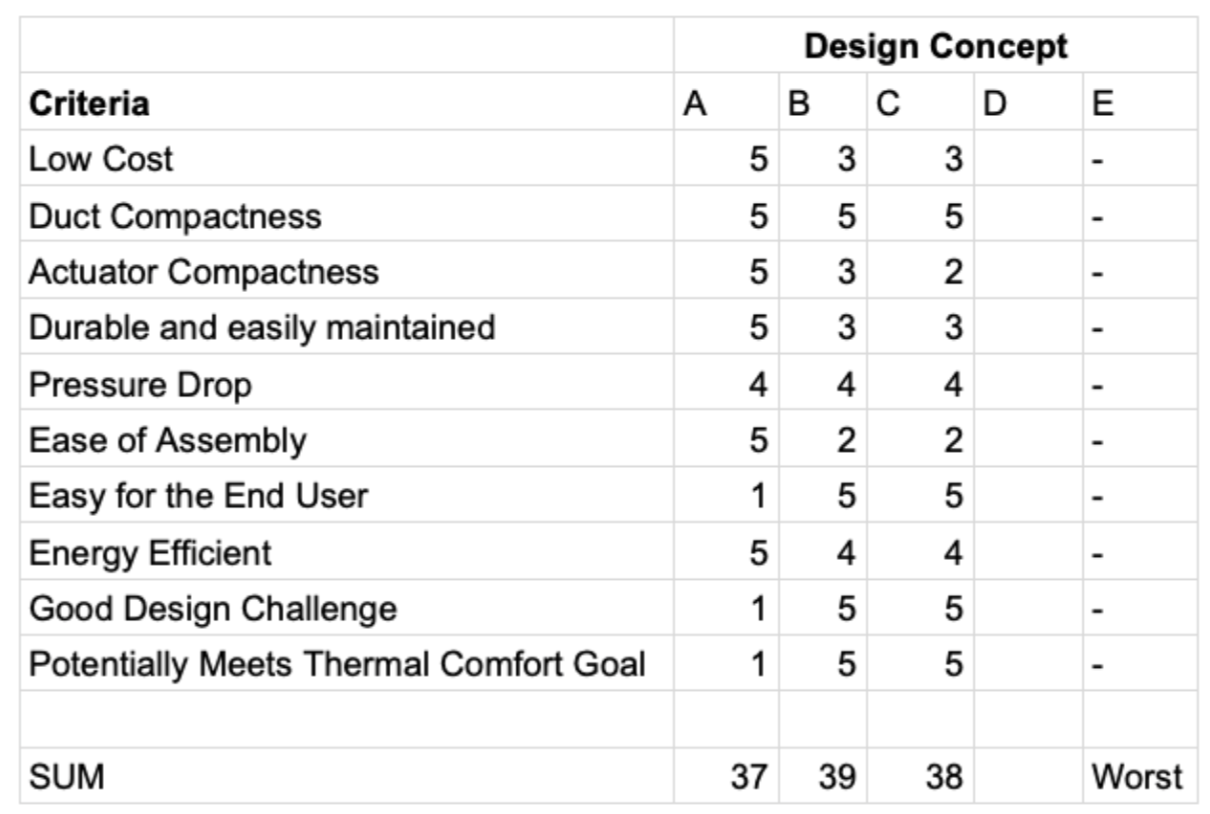
- We first identified five potential designs, four which involved a conventional damper and two without. The designs included: A. Manually operating the damper, B. Motor controlled with a single pulley or gear, C. Motor controlled through a direct drive, D. Purchasing a Variable Air-Volume System (VAV), E. Venturi Damper Design and F. off the shelf motorized damper that only has two positions (open/closed, no inbetween).
- The criteria we used to evaluate them included cost, overall duct compactness, actuator compactness, durability/maintenance, pressure drop, ease of assembly, difficulty of use for user, energy efficiency, a good design challenge for us, and how well would it reach our goal of thermal comfort.
- We decided to exclude designs D and E and instead focus on traditional dampers because they were both outside of the team’s budget. The motorized damper design F was also excluded early on because it would be much cheaper to use our own motor and we could have more control on the damper position and have it be partially closed or open.
- Thermal comfort team ultimately concluded that designing a gear system would be best for ease of assembly and compactness in comparison. We would buy a manual lever operated circular damper and add motorized control to the drive shaft
- Through our design selection process for the damper control, we determined that the off the shelf dampers that we would use for our design are not aerodynamic and would introduce unwanted pressure drop when there are multiple angular positions, which we are intending to do.
- This realization led us to designing an airfoil that we could attach to the off the shelf damper that would reduce unwanted pressure drop.
- Research was conducted on most aerodynamic shapes in air ducts and applied to our air duct constraints
- According to a Thesis study from 2021, the NA0100 airfoil design (see figure) is the most aerodynamic for HVAC systems [1]. Therefore, we used Sketchup to design and 3D printed a new damper with a NA0100 design to replace the commercial damper.
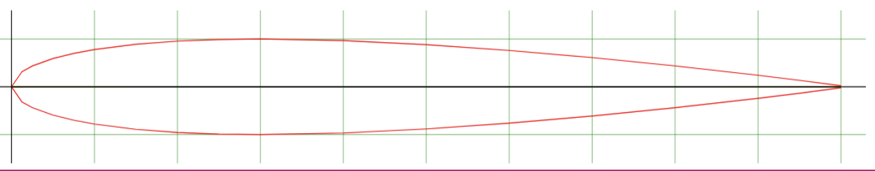
[1] Paudel, G. (2021). Comparative Study of Air Performance of Fully Ducted Damper for HVAC based on Different Blade Profiles. [Thesis, Pulchowk Campus]. https://elibrary.tucl.edu.np/handle/123456789/694