Thermal Storage
The process of generating concepts for thermal storage was a two-stage process. We first brainstormed ideas related to the best way to store PCM (phase change material), maximize heat transfer, and minimize duct size. Our brainstorming was guided by our functional requirements and two constraints. The two constraints were:
1) Must hold maximum of 5 gallons of PCM (prefer to be as close to 5 gal as possible)
2) Must fit inside of a 21’’ x 6” rectangular cross-section
Constraint 1 comes from the purchasing of the PCM from PureTemp. PureTemp only sold 5 gallon samples and bulk orders which were too large for our project. Constraint 2 comes from the physical size of the heat pump system purchased by the team.
Our brainstorming resulted in hand sketches of four different heat exchangers to hold PCM.
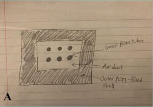
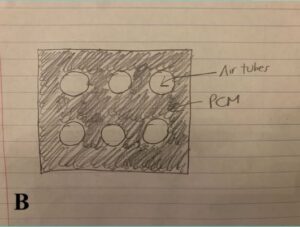
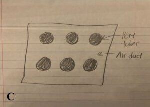
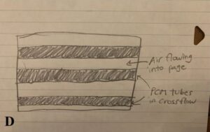
Design A is a front view of the heat exchanger with PCM surrounding the main duct and contained within the tubes inside the duct. Air is between the tubes and duct wall. The quantity of tubes in each hand design is for reference and not the actual number of tubes that would be present in a final design. Design B is a front view of the heat exchanger with air going through the tubes and PCM surrounding them in the duct. Design C is a front view of the heat exchanger with PCM in the tubes and air going around them through the duct. Design D is a front view of the heat exchanger with the tubes oriented sideways in a staggered configuration with crossflow (air flow direction perpendicular to PCM flow direction) air. Note that, in all of our designs, the PCM does not move and circulate. We did this to simplify the design and eliminate the need for a pump.
After consulting the pugh matrix we created as a team (see the Evaluation Criteria & Results section), we decided to analyze designs B and D more in depth. This is where the second stage of our concept generation process begins.
To analyze these design more in depth, we created four CAD designs as seen below:
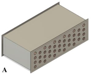
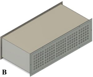
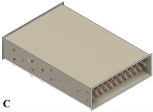
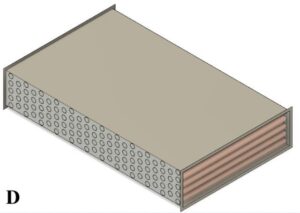
The first two designs are similar in that they both have air going through the tubes, have the same orientation of tubing, are about 12 inches long, and can hold approximately 5 gallons of PCM. The first design has more cross sectional area to flow through it, so we assumed there would be less pressure drop. Design 3 has PCM in the coiled tubes and air in crossflow. The drawback with this design is that it holds very little PCM which means we would have to extend the duct length greatly to meet the 5 gallon constraint, something we don’t want to do. The fourth design has PCM in tubes with air in crossflow. This design holds approximately 5 gallons of PCM and is 35 inches in length.
Thermal Comfort
To start brainstorming ideas for how we can design and construct an air duct system that can efficiently and effectively transport conditioned air, we looked at HVAC systems in both residential and commercial setups. We were specifically looking at shapes, sizes, and how the ducts are typically fastened together. This gave us a good understanding of how to start designing our air duct system. After viewing several typical systems, we also looked online for typical pricing information and what was available at low costs. We also consulted Professor Van Asselt to better understand the feasibility of some of our brainstormed ideas.
Standards we have to keep in mind when designing Air duct system:
International Mechanical Code Table 603.4: Set standards for metallic duct dimensions depending on shape, material, and pressure