Propulsion
A sub-team including Rithika Raghav, Jake Schwartz, & Eric Kraushaar
Concept Generation
In determining design ideas for the implementation of the robot’s Swim mechanism, several options were considered. Initially, research was conducted on propellers, specifically Fixed Pitch Propellers and Controlled Pitch Propellers. With Fixed Pitch Propellers, the propeller blades are fixed in terms of their angle / motion and with Controlled Pitch Propellers, the pitch of the propeller blades can be altered to influence the amount of thrust that occurs within the robot’s motion.
Moving on, a Hamilton Jet was considered. The Hamilton Jet functions utilizing an intake and outtake valve. Specifically, water enters the jet via the intake and is accelerated through the jet unit. A pumping unit increases the pressure of the water flow, after which it is discharged through a nozzle. More details regarding the Hamilton Jet can be seen above.
Concept Selection
A Hamilton Jet-style design was chosen over the Propeller design, given that it is highly advantageous when compared to propellers. However, challenges faced with respect to the Hamilton Jet were, whether or not the team would be purchasing or designing a Hamilton Jet. The feasibility challenges with designing the Hamilton Jet were far too broad. Thus, substantive research was conducted to determine that a Centrifugal Pump acts in a very similar manner to a Hamilton Jet.
A Centrifugal Pump’s main objective is to move fluid through a pressure differential. Specifically, water enters the pump through the casing and falls on the impeller blades. The impeller then rotates the water until it leaves the pump through the outtake. When traveling through the impeller, the water is gaining both velocity and pressure, allowing it to propel the robot forward.
In addition, it is highly advantageous in comparison to the propeller design. Specifically, it is reliable due to its relatively few moving parts, increasing the life of most components upon the design. Further, a Centrifugal Pump allows the robot to travel smoothly / quietly, as there is a lack of hull vibration and torque effects.
Concept Refinement
In determining the appropriate dimensions for the robot’s swim mechanism, the drag force of water flowing across the robot was calculated. Specifically, the robot was modeled as a 30 x 30 x 14 rectangular prism. Thus, the Drag Coefficient and Density of Water were assumed to be \(C_d = 1.5\) and \(\rho = 998 \ kg/m^3\), respectively. Additionally, the robot’s velocity through the water was assumed to be 4.5 mph. Subsequently, the drag force was determined to be:

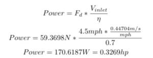
Utilizing the above drag force, the power required for the robot to navigate through the water was determined. Note that the Centrifugal Pump does not have perfect efficiency; thus, its efficiency was assumed to be 0.7.

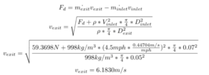
Knowing the drag force and power required to navigate the robot through the water, the appropriate outlet water velocity was calculated. Note that the outlet velocity must be higher than the inlet velocity for the robot to propel forward. At this stage, the inlet and outlet diameters of the pump were assumed and iterated on. The final inlet / outlet diameters were settled to be 0.07 m and 0.05 m, respectively.

The above outlet velocity was then utilized to calculate the flow rate from the outlet of the pump, as can be observed below.

Finally, the speed of impeller rotation was determined using the exit flow rate calculated above.

See some of our first semester accomplishments here!
